


Chapter 1 Performance Tests
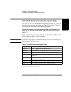
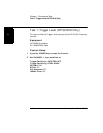
Test 1: Trigger Level (HP 53181A Only)
1-50 Assembly-Level Service Guide
1
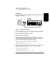
7 In the Counter’s Channel 1 Trigger/Sensitivity menu, change the
SLOPE to NEG.
8 On the Counter, press Run key.
9 Set the HP 3325B DC OFFSET to +60 mV.
10 Now, decrement the offset on the HP 3325B by
−
1 mV until the
Counter’s
Gate
annunciator flashes and continue decrementing
until the Counter displays approximately 1 MHz.
Observe the offset value on the display of the HP 3325B.
Record the value__________ mV.
11 Add the lower peak voltage (
−
40mV) of the 80 mVp-p signal to the
offset value in step 10 (for example, 21 mV
−
40 mV =
−
19 mV.)
This result is the lower hysteresis level.
Record the lower hysteresis level __________ mV.
12 Now, add the upper hysteresis value (recorded in step 6 )and
lower hysteresis value (recorded in step 11).
This is the trigger level; it should be 0.0 V ±15 mV.
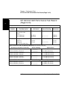
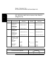
13 Record the trigger level value in the Performance Test Record
(Test 1, Line 1).