


Chapter 8 HP 53181A Specifications
General Information
Assembly-Level Service Guide 8-11
8
General Information
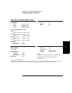
Save and Recall: Up to 20 complete instrument setups may be saved and recalled later. These setups are retained when
power is removed from the counter.
Rack Dimensions (HxWxD): 88.5 mm x 212.6 mm x 348.3 mm
Weight: 3.5 kg maximum
AC Line Supply DC Supply (Option 002 Only)
Power Supply Voltage: 100 to 120 VAC ±10% - 50, 60 or 400 Hz ±10% 10 to 32 VDC, 3-pin male XLR connector
220 to 240 VAC ±10% - 50 or 60 Hz ±10%
AC Line Voltage Selection: Automatic Option 002 may not be ordered with Option 060
Power Requirements: 170 VA maximum (30 W typical) 4A initial inrush at 10 VDC
3A max, once stabilized
Operating Environment: 0° C to 55° C
Storage Environment: –40° C to 71° C
Remote Interface: HP-IB (IEEE 488.1-1987, IEEE 488.2-1987)
HP-IB Interface Capabilities: SH1, AH1, T5, TE0, L4, LE0, SR1, RL1, PP0, DC1, DT1, C0, E2
Remote Programming Language: SCPI-1992.0 (Standard Commands for Programmable Instruments)
Safety: Designed in compliance with IEC 1010-1, UL 3111-1 (draft), CAN/CSA 1010.1
EMC: CISPR-11, EN50082-1, IEC 801-2, -3, -4
Electrostatic Discharge and Fast Transient/Burst Immunity Testing: When the product is operated at
maximum sensitivity (20 mVrms) and tested with 8kV AD according to IEC801-2 or with 1kV power line
transients according to IEC 801-4, frequency miscounts may occur that will affect measurement data
made during these disturbances.
Radiated Immunity Testing: When the product is operated at maximum sensitivity (20 mVrms) and tested
at 3 V/m according to IEC 801-3, external 100 to 200 MHz electric fields may cause frequency miscounts.
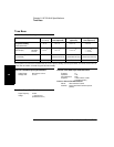
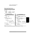
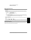
RS-232C: The rear-panel RS-232 connector is a 9-pin connector (DB-9, male). You can connect the universal
counter to any terminal or printer with a properly configured DTE connector (DB-25). You can use a
standard interface cable (HP part number 24542G or 24542H). Data is “output only”; the instrument can
not be programmed via the RS-232 interface.
Note on Pin 4: May be used as either a DTR signal or an indication of measurement in-limit as configured by the Utility menu.
When used as an in-limit indicator, the signal will be high for every measurement within the user set limits.
Pin Number Type Description
2 Input Receive Data (RxD) (for Xon/Xoff only)
3 Output Transmit Data (TxD)
4 Output Data Terminal Ready (DTR)
Measurement In-Limit Signal
5 — Signal Ground
6 Input Data Set Ready (DSR)
* All other pins: no connection
1234 5
6789