


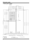
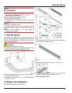
Fig. 41
u
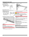
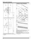
With the hinge of the upper soft stop unit facing the
door hinge side, engage the soft stop unit (A) and
swivel inwards (B).
w
The holes on the left and right must lie exactly above
each other.
u
Tighten soft stop unit (2 x Torx 15)
Fig. 41 (7)
.
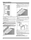
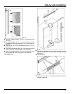
Note
u
Follow the correct sequence. First hang the panel over
the damper bracket, then the cover.
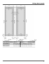
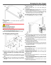
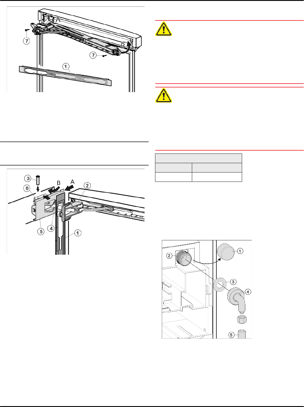
Fig. 42
u
Hook panel
Fig. 42 (1)
into the damper bracket
Fig. 42 (4)
such that the detent hooks are pointing inwards and the
front side is facing the appliance.
u
Push on cover
Fig. 42 (5)
from the outside (A) and pivot
over the bearing part
Fig. 42 (8)
(B).
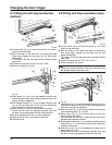
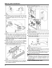
u
Place cover
Fig. 42 (5)
on top and allow to snap into
place until the first notch.
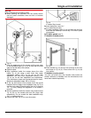
w
The openings for the bolts lie above each other after
positioning the damper bracket.
u
Pull damper bracket
Fig. 42 (4)
towards bearing part and
insert bolt
Fig. 42 (3)
from above such that the square is
resting in the recess.
u
Now snap cover
Fig. 42 (5)
completely into place on the
bearing part
Fig. 42 (8)
.
w
Check that the cover is positioned correctly such that
the door can close properly and the bolt is secured.
u
Remove locking device
Fig. 42 (2)
by twisting it.
u
Tighten spacer
Fig. 39 (10)
.
u
Snap panel
Fig. 42 (1)
into place on the door.
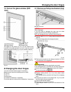
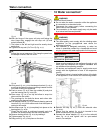
10 Water connection*
WARNING
Electrical Shock Hazard!
u
Do not make the water connection while the appliance
is connected to an electrical outlet.
u
Disconnect the water supply before connecting the
water lines for the IceMaker.
u
The connection to the water supply may only be made
by a trained and licensed plumber.
WARNING
Poisoning Hazard!
u
The water quality must comply with the drinking water
regulations for the geographical area where the
appliance is located.
u
The IceMaker is designed exclusively to make ice
cubes in quantities needed by a household and must
only be operated with water appropriate for this purpose.
Water pressure:
psi MPa (bars)
21.76 to 87.02 0.15 to 0.6 (1.5 to 6)
- Water must be supplied to the appliance through a cold
water pipe that complies with hygiene standards and
can withstand the operating pressure.
- All devices and equipment used to supply water must
comply with the regulations in force in the respective
country.
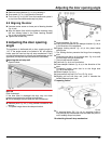
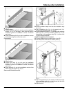
- The solenoid valve is located at the bottom of the back
of the appliance. It has a metric R3/4 connecting thread.
Fig. 43
u
Remove the cap
Fig. 43 (1)
from the solenoid valve
Fig. 43 (2)
.
u
Ensure that the gasket
Fig. 43 (3)
is inserted in the
elbow connection
Fig. 43 (4)
supplied.
u
Connect the elbow adapter
Fig. 43 (4)
to the solenoid
valve
Fig. 43 (2)
and tighten with an open-ended
wrench, for example.
Water connection
24