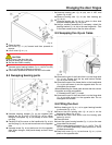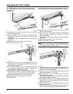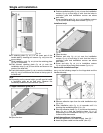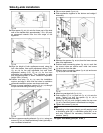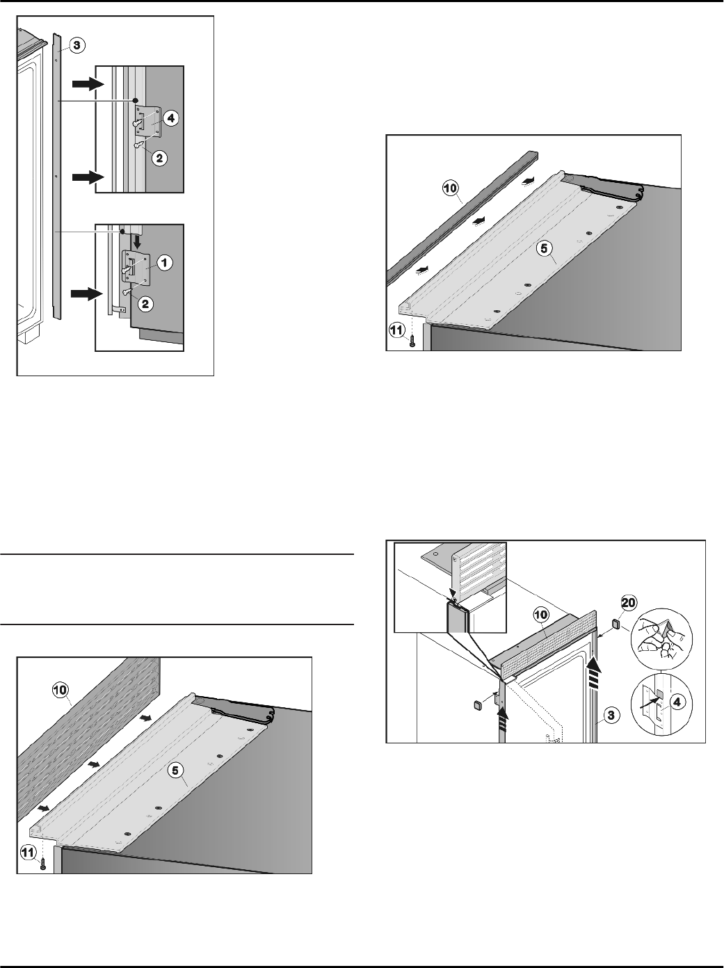
Fig. 48
u
Fit retaining plate
Fig. 48 (1)
to the lower part of the
handle side by inserting two screws
Fig. 48 (2)
into the
pre-cut holes.
u
Slide installation strip
Fig. 48 (3)
into the retaining plate
Fig. 48 (1)
from above.
u
Push second retaining plate
Fig. 48 (4)
onto the
installation strip
Fig. 48 (3)
from above and screw to the
center of the side wall.
u
Push third retaining plate
Fig. 48 (4)
onto the installation
strip
Fig. 48 (3)
from above and screw to the top part of
the side wall.
Note
u
Depending on the recess height you will need to install
a ventilation grille or an end strip. Observe the
necessary ventilation cross-sections (see 5) .
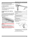
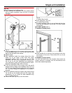
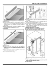
Fit upper ventilation grille (80”):
Fig. 49
u
Open the door.
u
Position ventilation grille
Fig. 49 (10)
over the installation
contour
Fig. 49 (5)
and align it such that the holes in
ventilation grille and installation contour are above
each other.
u
Screw ventilation grille
Fig. 49 (10)
to installation contour
Fig. 49 (5)
from below using three screws
Fig. 49 (11)
.
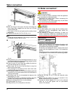
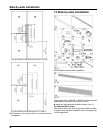
Install end strip:
Fig. 50
u
Open the door.
u
Position end strip
Fig. 50 (10)
over the installation
contour
Fig. 50 (5)
and align it such that the holes in
ventilation grille and installation contour are above
each other.
u
Screw end strip
Fig. 50 (10)
to installation contour
Fig. 50 (5)
from below using three screws
Fig. 50 (11)
.
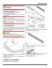
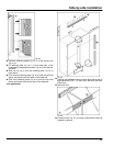
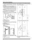
Secure side installation strips:
carry out the following steps for the hinge-side and the
handle-side strip:
Fig. 51
u
Remove adhesive tape from the side installation strip
Fig. 51 (3)
.
u
Push installation strip
Fig. 51 (3)
upwards until it is
touching the ventilation grille
Fig. 51 (10)
.
u
Glue the adhesive plates
Fig. 51 (20)
above the retaining
plate
Fig. 48 (1)
and the retaining plates
Fig. 51 (4)
respectively to the installation strip
Fig. 51 (3)
such that
it cannot slide downwards.
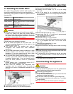
Install the appliance in the recess:
u
Connect appliance to the water supply (see 10) .*
u
Insert the power cable into the socket (see 15) .
Single unit installation
26


