Accessories
7-17
Setup
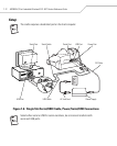
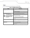
Table 7-2 lists the requirements for setting up and using the VCD9000.
Table 7-2. VCD9000 Setup Requirements
Feature Requirements
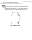
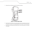
Mounting (See page 7-18) Four 8-32 X 1” long screws with locking washers (provided as part of the
cradle).
Four #8 washers recommended.
A drill with a #6 drill bit (0.204”).
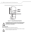
Power Connection (See page 7-20)
For continued protection
agains risk of fire, replace only
with same type and rating of
fuse according to the input
voltage used.
Power input cable (provided) connects to vehicle power.
UL-listed in-line fuse rated 4A or 5A (both included), must be used if not
connecting to vehicle’s fuse panel.
For 12 V operation use UL-listed 5A fuse (included).
For 24 V operation use UL-listed 4A fuse (included).
In-line fuse holder (included), must be used if not connecting to vehicle’s
fuse panel.
Serial Connection (See page 7-23) DB9 female serial cable (some external devices require a null modem
cable). The port is a Standard RS-232 for direct connection to a serial
device.
Communication An MC9000 Series mobile computer.
Setup of mobile computer and external device (as determined by the
application used).


