


Part I 1-3
Teledyne Analytical Instruments
Thermal Conductivity Analyzer Part I: Control Unit
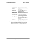
• Wide range of custom applications, ranges, and linearization.
• Microprocessor based electronics: 8-bit CMOS microprocessor
with 32 kB RAM and 128 kB ROM.
• Auto and remote calibration capabilities.
• Four analog outputs: two for measurement (0–1 V dc and Isolat-
ed 4–20 mA dc) and two for range identification.
• Compact and versatile design: Small footprint, yet internal com-
ponents are accessible.
1.4 Model Designations
The Model 2010B is ordinarily custom programmed at the factory to fit the
customer’s application. Many parameters, including the number of channels, the
gas application, the materials specification of the sampling system, and others,
are options. The most common options, are covered in this manual. See the
Specific Model Information checklist in the front matter of this manual for those
that apply to your Model 2010B analyzer. Some standard models that are not
covered in this manual are listed here.
Models 2000A: Both analysis section and control unit are in a single
general purpose enclosure.
Models 2020: Both the analysis section and control unit are in a single
explosion proof enclosure.
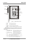
1.5 Operator Interface (Front Panel)
The standard 2010B is housed in a rugged metal case with all controls and
displays accessible from the front panel. See Figure 1-1. The front panel has
thirteen buttons for operating the analyzer, a digital meter, and an alphanumeric
display. They are described briefly here and in detail in the Operations chapter
of this manual.
Function Keys: Six touch-sensitive membrane switches are used to
change the specific function performed by the analyzer:
• Analyze Perform analysis for target-gas content of a sample
gas.
• System Perform system-related tasks (described in detail in
chapter 4, Operation.).