


4 Maintenance Model 2010B
4-4: Part II Teledyne Analytical Instruments
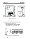
4.5 Cell, Heater, and/or Thermistor
Replacement
The Thermal Conductivity Cell, with its Heater and Thermistor, is
mounted inside the insulated cell compartment, inside the analysis unit. To
remove these components, you must first remove screw on the cover, and
the customer interface.
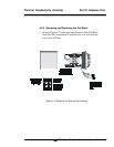
4.5.1 Removing the Cell Compartment
WARNING: IF THE MODEL 2010B ANALYZER HAS BEEN USED
WITH TOXIC GASES, FLUSH IT THOROUGHLY
BEFORE PERFORMING THIS PROCEDURE.
WARNING: DISCONNECT ALL POWER TO THE MODEL 2010B
BEFORE PERFORMING THIS PROCEDURE.
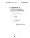
Remove the t/c cell as follows:
a. Verify that the power has been removed from the analysis unit
prior to removing cover.
b. Verify that the analysis unit is free from any toxic gas prior
disconnecting any plumbing.
c. Remove the screw on lid and the six #6 screws securing the
interface cover panel.
d. Remove the cover panel and the four 3/4" #6 stands-off securing
the 1
st
interface PCB.
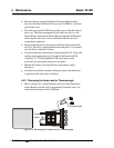
e. Remove the 1
st
PCB and the four 7/16" #6 stand-off securing the
2
nd
interface PCB.
f. Unplug the heater from J3, and the sensor connectors from the
sensor connector J4, and J2, on the upper interface PCB.
Remove the 2
nd
PCB. Remove the two #10 screws from the
sensor retaining bracket located at the top of the sensor.
Disconnect the gas fitting and remove the sensor from the
analysis unit.
g. Reassemble in the reverse order, verify that there are no gas leaks
prior to returning the unit to service.