


Part I 2-5
Thermal Conductivity Analyzer Part I: Control Unit
Teledyne Analytical Instruments
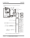
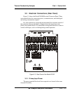
In the presence of dissimilar gases the sensor generates a differential
voltage across its output terminals. A differential amplifier converts this
signal to a unipolar signal, which is amplified in the second stage, variable
gain amplifier, which provides automatic range switching under control of
the CPU. The output from the variable gain amplifier is sent to an 18 bit
analog to digital converter.
The digital concentration signal along with input from the Gas Selector
Panel is processed by the CPU and passed on to the 12-bit DAC, which
outputs 0-1 V dc Concentration and Range ID signals. An voltage-to-current
converter provides 4-20 mA dc concentration signal and range ID outputs.
The CPU also provides appropriate control signals to the Displays,
Alarms, and External Valve Controls, and accepts digital inputs for external
Remote Zero and Remote Span commands. It monitors the power supply
through an analog to digital converter as part of the data for the system
failure alarm.
The RS-232 port provides two-way serial digital communications to
and from the CPU. These, and all of the above electrical interface signals are
described in detail in chapter 3 Installation.
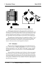
2.4. Temperature Control
For accurate analysis the sensor of this instrument is temperature con-
trolled to 50
o
C.
The Temperature Control keeps the temperature of the measuring cell
regulated to within 0.1 degree C. A thermistor is used to measure the tem-
perature, and a zero-crossing switch regulates the power in a cartridge-type
heater. The result is a sensor output signal that is temperature independent.
A second temperature control system is used to maintain the Analysis
Unit internal temperature at 22
0
C minimum.