


2 Installation Model 2010B
2-2: Part II Teledyne Analytical Instruments
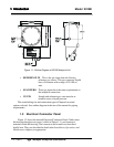
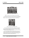
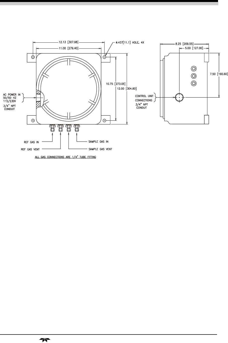
Figure 3-1: 2010 Analysis Unit with Auto-Cal & Gas Panel options
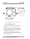
2-3 Sample System Design
Gas Connector and Selector Panels for specific applications are avail-
able at additional cost . These panels are designed to substitute a standard
front panel.
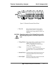
For those customers wishing to incorporate their own sample system,
electronic input/output ports are provided on the rear panel for the operation
of solenoid valves under the complete control of the Model 2010B electron-
ics. See section 3.3. The recommended system piping schematic is included
among the drawings at the rear of the manual
For best results, use the recommended piping system. Select a
flowmeter that can resolve 0.08 scfh (40-50 cc/min) for the reference path of
the analyzer, and select a flowmeter that can resolve 0.3 scfh (150 cc/min)
for the sample path of the analyzer.