


Teledyne Analytical Instruments
3 Installation Model 2010B
3-6 Part I
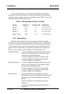
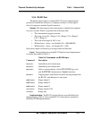
To provide an indication of the range, the Range ID analog output
terminals are used. They generate a steady preset voltage (or current when
using the current outputs) to represent a particular range. Table 3-2 gives the
range ID output for each analysis range.
Table 3-2: Analog Range ID Output—Example
Range Voltage (V) Current (mA) Application
Range 1 0.25 8 0-1 % H
2
in N2
Range 2 0.50 12 0-10 % H
2
in N2
Range 3 0.75 16 0-1 % H
2
in Air
Range 4 (Cal) 1.00 20 0-1 % H
2
in N2
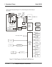
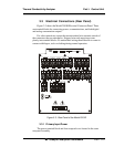
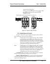
3.3.4 Alarm Relays
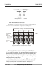
The three alarm-circuit connectors are spring terminals for making
connections to internal alarm relay contacts. Each provides a set of Form C
contacts for each type of alarm. Each has both normally open and normally
closed contact connections. The contact connections are indicated by dia-
grams on the rear panel. They are capable of switching up to 3 amperes at
250 V ac into a resistive load. See Figure 3-5. The connectors are:
Threshold Alarm 1: • Can be configured as high (actuates when concen-
tration is above threshold), or low (actuates when
concentration is below threshold).
• Can be configured as fail-safe or non-fail-safe.
• Can be configured as latching or nonlatching.
• Can be configured out (defeated).
Threshold Alarm 2: • Can be configured as high (actuates when concen-
tration is above threshold), or low (actuates when
concentration is below threshold).
• Can be configured as fail-safe or non-fail-safe.
• Can be configured as latching or nonlatching.
• Can be configured out (defeated).
System Alarm: Actuates when DC power supplied to circuits is
unacceptable in one or more parameters. Permanently
configured as fail-safe and latching. Cannot be de-
feated.
Actuates when cell can not balance during zero
calibration.
Actuates when span parameter out off its limited
parameter.