


Teledyne Analytical Instruments
Thermal Conductivity Analyzer Part I: Control Unit
Part I 3-1
Installation
Installation of the Model 2010B Analyzer includes:
1. Unpacking
2. Mounting
3. Gas connections
4. Electrical connections
5. Testing the system.
3.1 Unpacking the Analyzer
The analyzer is shipped ready to install and prepared for operation.
Carefully unpack the analyzer and inspect it for damage. Immediately report
any damage to the shipping agent.
3.2 Mounting the Control Unit
The Model 2010B Control Unit is designed for bulkhead mounting in
general purpose area, NOT for hazardous environments of any type. The
Control Unit is for indoor/outdoor use.
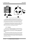
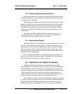
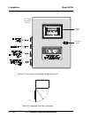
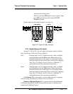
Figure 3-1 is an illustration of the 2010B standard front panel and
mounting bezel. There are four mounting holes—one in each corner of the
rigid frame. See the outline drawing, at the back of this manual for overall
dimensions.
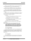
All operator controls are mounted on the inner control panel, which is
hinged on the left edge and doubles as a door to provide access to the internal
components of the instrument. The door will swing open when the button of
the latch is pressed all the way in with a narrow gauge tool (less than 0.18
inch wide), such as a small hex wrench or screwdriver Allow clearance for
the door to open in a 90-degree arc of radius 11.75 inches. See Figure 3-2.