


Part I 2-3
Thermal Conductivity Analyzer Part I: Control Unit
Teledyne Analytical Instruments
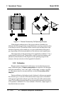
2.2.3 Effects of Flowrate and Gas Density
Because the flowrate of the gases in the chambers affects their cooling
of the heated filaments, the flowrate in the chambers must be kept as equal,
constant, and low as possible.
When setting the sample and reference flowrate, note that gases lighter
than air will have an actual flowrate higher than indicated on the flowmeter,
while gases heavier than air will have an actual flowrate lower than indi-
cated. Due to the wide range of gases that are measured with the Thermal
Conductivity Analyzer, the densities of the gases being handled may vary
considerably.
Then, there are limited applications where the reference gas is in a
sealed chamber and does not flow at all. These effects must be taken in
consideration by the user when setting up an analysis.
2.2.4 Measurement Results
Thermal conductivity measurements are nonspecific by nature. This fact
imposes certain limitations and requirements. If the user intends to employ
the analyzer to detect a specific component in a sample stream, the sample
must be composed of the component of interest and one other gas (or spe-
cific, and constant, mixture of gases) in order for the measured heat-transfer
differences to be nonambiguous.
If, on the other hand, the user is primarily interested in the purity of a
process stream, and does not require specific identification of the impurity,
the analyzer can be used on more complex mixtures.
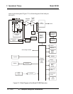
2.3 Electronics and Signal Processing
The Model 2010B Thermal Conductivity Analyzer uses an 8031
microcontroller, Central Processing Unit—(CPU) with 32 kB of RAM and
128 kB of ROM to control all signal processing, input/output, and display
functions for the analyzer. System power is supplied from a universal power
supply module designed to be compatible with any international power
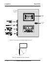
source. (See Major Internal Components in chapter 5 Maintenance for the
location of the power supply and the main electronic PC boards.)
The signal processing electronics including the microprocessor, analog
to digital, and digital to analog converters are located on the Motherboard at
the bottom of the case. The Preamplifier board is mounted on top of the
Motherboard as shown in the figure 5.4. These boards are accessible after