


2-4 Part I
2 Operational Theory Model 2010B
Teledyne Analytical Instruments
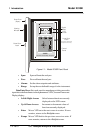
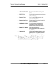
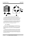
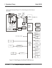
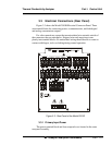
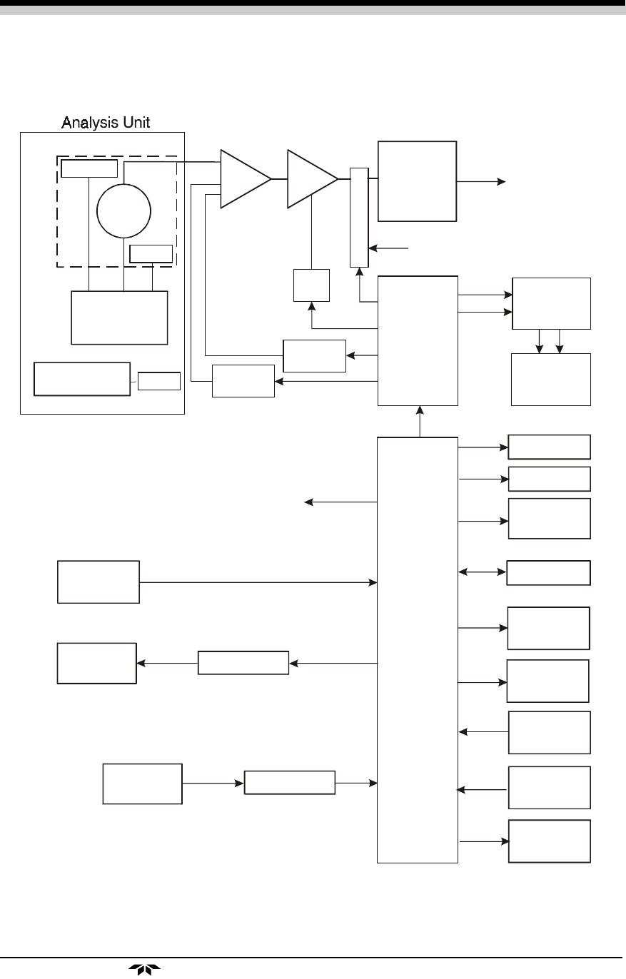
removing the back panel. Figure 2-2 is a block diagram of the Analyzer
electronics.
Figure 2-2: Block Diagram of the Model 2010B Electronics
Thermistor
Sensor
Heater
Temperature
Control
Fine
Adjustment
Coarse
Adjustment
Auto-
Range
M
U
X
A to D
Converter
Digitial to
Analog
Converter
(DAC)
0-1 V dc
Concentration
and Range
4-20 mA dc
Concentration
and Range
Differential
Amplifier
Variable
Gain
Amplifier
Central
Processing
Unit
(CPU)
Alarm 1
Alarm 2
System
Failure
Alarm
RS-232
Range
Contacts (4)
External
Valve
Control
Remote Span
Control
Remote Zero
Control
Cal
Contact
Keyboard
Displays
Processing
Selt-Test Signal to MUX
Power
Supply
A to D Conv
To CPU
Temperature
Control
Heater