


Part I 1-5
Teledyne Analytical Instruments
Thermal Conductivity Analyzer Part I: Control Unit
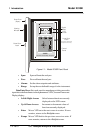
Digital Meter Display: The meter display is a VFD device that
produces large, bright, 7-segment numbers that are legible in any lighting. It
produces a continuous trace readout from 0-9999 ppm or a continuous percent
readout from 1-100 %. It is accurate across all analysis ranges.
Alphanumeric Interface Screen: The VDF screen is an easy-to-use
interface between operator and analyzer. It displays values, options, and
messages that give the operator immediate feedback.
Standby Button: The Standby turns off the display and outputs,
but circuitry is still operating.
CAUTION: The power cable must be unplugged to fully
disconnect power from the instrument. When
chassis is exposed or when access door is open
and power cable is connected, use extra care to
avoid contact with live electrical circuits.
Access Door: For access to the thermal conductivity sensor or the front
panel electronics, the front panel swings open when the latch in the upper right
corner of the panel is pressed all the way in with a narrow gauge tool. Accessing
the main electronics circuit board requires unfastening rear panel screws and
sliding the electronics drawer out of the case. (See chapter 5.)
1.6 Recognizing Difference Between LCD &
VFD
LCD (Liquid Crystal Display) has GREEN background with BLACK
characters. VFD has DARK background with GREEN characters. In the case
of VFD (Vacuum Fluorescent Display) - NO CONTRAST ADJUSTMENT IS
NEEDED.
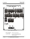
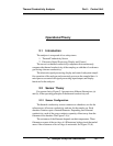
1.7 Equipment Interface (Rear Panel)
The rear panel, shown in Figure 1-2, contains the electrical connectors for
external input and output. The connectors are described briefly here and in detail
in chapter 3, Installation.