


Teledyne Analytical Instruments
Thermal Conductivity Analyzer Part I: Control Unit
Part I 3-9
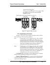
3.3.8 RS-232 Port
The digital signal output is a standard RS-232 serial communications
port used to connect the analyzer to a computer, terminal, or other digital
device. It requires a standard 9-pin D connector.
Output: The data output is status information, in digital form, updated
every two seconds. Status is reported in the following order:
• The concentration in ppm or percent
• The range in use (01 = Range 1, 02 = Range 2, 03 = Range 3,
CAL = Range 4)
• The scale of the range (0-100 %, etc)
• Which alarms—if any—are disabled (AL–x DISABLED)
• Which alarms—if any—are tripped (AL–x ON).
Each status output is followed by a carriage return and line feed.
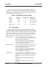
Input: The input functions using RS-232 that have been implemented
to date are described in Table 3-3.
Table 3-3: Commands via RS-232 Input
Command Description
as<enter> Immediately starts an autospan.
az<enter> Immediately starts an autozero.
rp<enter> Allows reprogramming of the APPLICATION (gas use)
and ALGORITHM (linearization)
System
functions.
st<enter> Toggling input. Stops/Starts any status message output from
the RS-232, until st<enter> is sent again.
rm1<enter> Range manual 1
rm2<enter> Range manual 2
rm3<enter> Range manual 3
rm4<enter> Range manual CAL
ra<enter> Range auto
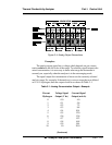
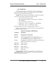
Implementation: The RS-232 protocol allows some flexibility in its
implementation. Table 3-4 lists certain RS-232 values that are required by
the Model 2010B implementation.