


1-2: Part II Teledyne Analytical Instruments
1 Introduction1 Introduction
1 Introduction1 Introduction
1 Introduction Model 2010B
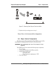
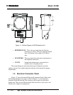
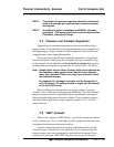
Figure 1-1: Outline Diagram of 2010B Analysis Unit
• REFERENCE IN This is the gas input from the flowing
reference gas source. This gas connector should
have a flowmeter with a range of 20-100 cc/
min.
• SPAN/ZERO These gas inputs have the same requirements as
the sample in connection.
• VENTS Sample and reference gas vents must be re-
turned to areas of equal pressure.
The actual tubing size and connection type will depend on actual
options selected. See outline diagram in the rear of the manual for piping
requirements.
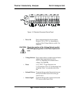
1.3 Electrical Connector Panel
Figure 1-2 shows the internal Electrical Connector Panel. Cables enter
the housing through access ports (visible in Figure 1-1), and connect to
terminals inside the housing. The connectors and controls are described
briefly here. They are described in detail in the Installation, Operation, and
Maintenance chapters, as appropriate.