


Thermal Conductivity Analyzer Part II: Analysis Unit
Teledyne Analytical Instruments Part II: 2-1
Installation
Installation of the Model 2010B Analyzer includes:
1. Unpacking, mounting, and interconnecting the Control Unit and
the Analysis Unit
2. Making gas connections to the system
3. Making electrical connections to the system
4. Testing the system.
2.1 Unpacking the Analysis Unit
The analyzer is shipped with all materials needed to install and prepare the
system for operation. Carefully unpack the Analysis Unit and inspect it for
damage. Immediately report any damage to the shipping agent.
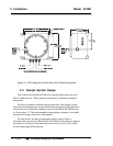
2.2 Mounting the Analysis Unit
The Model 2010B Analysis Unit is for use in Class 1, Division 1,
Groups C and D, hazardous environments (group B available). The actual
class is limited by the flame arrestor option.
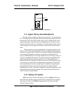
The standard model is designed for bulkhead mounting. Overall dimen-
sions of the Analysis Unit will vary depending on options. The maximum
footprint will be 19″ × 12″, and maximum height 9.4″. An Outline Drawing
at the back of this manual, gives the correct mounting dimensions for your
unit.
Note: The housing, including the cover, protrudes 8.6 to 9.4
inches
from the base on which it is mounted. Enough clearance is
required in front of the cover to allow the cover to be re-
moved.
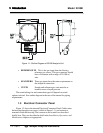
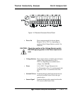
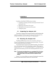
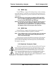
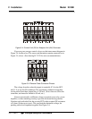
Figure 3-1 is a view with the cover removed showing the external Gas
Connector Panel and the internal Electrical Connector Panel.