


2 Installation Model 2010B
2-6: Part II Teledyne Analytical Instruments
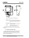
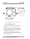
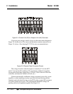
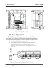
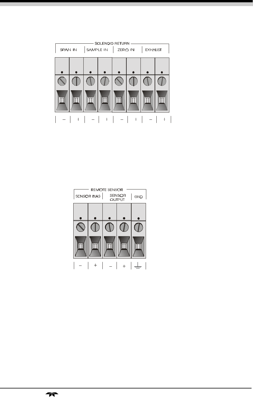
Figure 3-4: Control Unit (CU) to Analysis Unit (AU) Connector
If you use your own gas control valves, use the interconnect diagram in
Figure 3-4 for the valves. The sensor and thermistor remain connected as in
Figure 3-5, above. (See drawing D-73170 for wire recommendations.)
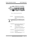
Figure 3-5: Remote Probe Connector Pinouts
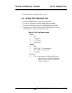
The voltage from the solenoid outputs is nominally 0 V for the OFF
and 15 V dc for the ON conditions. The maximum combined current that
can be pulled from these output lines is 100 mA. (If two lines are ON at the
same time, each must be limited to 50 mA, etc.)
If more current and/or a different voltage is required, use a relay, power
amplifier, or other matching circuitry to provide the actual driving current.
Note that each individual line has a series FET with a nominal ON resistance
of 5 ohms (9 ohms worst case). This can limit the obtainable voltage, de-
pending on the load impedance applied. See Figure 3-6.