


4 Maintenance Model 2010B
4-6: Part II Teledyne Analytical Instruments
b. Remove the two screws holding the front mounting bracket—
they also hold the Cell Block Cover to the Cell Block—and then
pull off the cover.
c. Turn the uncovered Cell Block assembly over so that the bottom
faces you. The black rectangular block with four screws is the
Heater Block. Separate the Heater Block from the Cell Block by
removing the four screws. Leave the Heater Block electrical
connections connected.
d. Remove the four screws from each of the black plates that hold
the Cell. The Cell is sandwiched between the plates. You should
now be able to slide the Cell free.
e. Leave the electrical connections connected at the Cell. Unlace the
cabling, and unplug the grey Cell cable at the Interface PCB
connector, J3. The Preamplifier PCB can be more easily
accessed by removing the analyzer's rear panel.
f. Replace the cell by reversing the above procedure, steps a
through e.
g. On analyzers with the sealed air reference option, the thermistor
is epoxied to the front of the cell block.
4.5.3 Removing the Heater and/or Thermocouple
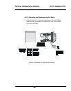
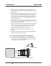
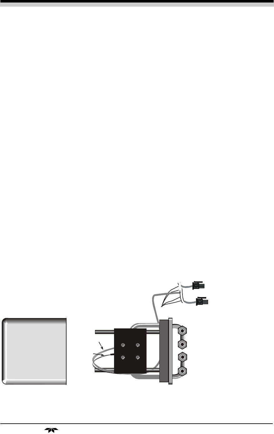
a. Refer to Figure 4-4, which illustrates removal of the Thermistor
and/or Heater from the Cell Compartment. Exploded view is as
seen from the bottom of the Cell Block.
Figure 4-4: Removing the Heater and/or Thermocouple
Thermistor
Heater
To Interface Board