


Teledyne Analytical Instruments
Thermal Conductivity Analyzer Part I: Control Unit
Part I 3-7
Actuates when self test fails.
(Reset by pressing
I/O
button to remove power. Then
press
I/O
again and any other button EXCEPT
System
to resume.
Further detail can be found in chapter 4, section 4-5.
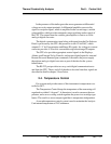
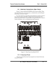
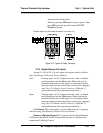
Figure 3-5: Types of Relay Contacts
3.3.5 Digital Remote Cal Inputs
Accept 0 V (off) or 24 V dc (on) inputs for remote control of calibra-
tion. (See Remote Calibration Protocol below.)
Zero: Floating input. 5 to 24 V input across the + and – terminals
puts the analyzer into the
Zero
mode. Either side may be
grounded at the source of the signal. A synchronous signal
must open and close the external gas control valves appropri-
ately. See 3.3.9 Remote Probe Connector. (With the –C
option, the internal valves operate automatically.)
Span: Floating input. 5 to 24 V input across the + and – terminals
puts the analyzer into the
Span
mode. Either side may be
grounded at the source of the signal. A synchronous signal
must open and close the external gas control valves appropri-
ately. See 3.3.9 Remote Probe Connector. (With the –C
option, the internal valves operate automatically.)
Cal Contact: This relay contact is closed while analyzer is spanning
and/or zeroing. (See Remote Calibration Protocol below.)
Remote Calibration Protocol: To properly time the Digital Remote
Cal Inputs to the Model 2010B Analyzer, the customer's controller must
monitor the Cal Relay Contact.