MODEL C24EA - CONTROL BOARD
F35453 (July 2008) Page 34 of 68
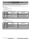
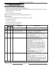
STEAM GENERATOR OPERATIONAL STATUS
(LED INDICATORS)
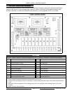
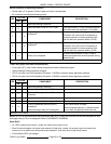
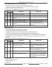
Use the tables below to determine the operational status of a component or condition by utilizing the LED
indicators on the board. The sections are divided according to their operational step.
NOTE: If steamer power switch is off when line voltage applied, the steamer enters a timed drain cycle then shuts
off.
Starting Conditions
• Power and water supplied to steamer.
• Power switch (1S) off.
• Delime switch (2S) off (center position).
• Steamer previously operated and drain cycle timed out.
LED
STATUS
COMPONENT DESCRIPTION
ON OFF
1 X Power to control board (120V) Main transformer (1T) powered.
9 X Power to drain (TDR) Relay timed out, no output to drain circuit.
12 X Vacuum relief solenoid (2SOL) energized.
Pressure switch closed (2PAS). Allows
venting of steam generator during fill.
13 X Power to delime 1 (TDR) Relay timed out, no output to delime circuit.
All other LED's are off.
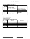
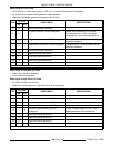
Power Switch on
• Power light (3LT) (amber) on.
• HL LED is on. Water level control powered.
• Water fills steam generator at fast fill rate.
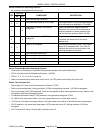
LED
STATUS
COMPONENT DESCRIPTION
ON OFF
1 X Same as starting conditions
9 X Power removed from drain (TDR) K4 relay energized. K4-6/2 contacts open.
12 X Same as starting conditions
13 X Power removed from delime 1 (TDR) K4 relay energized. K4-6/2 contacts open.
All other LED's are off.


