


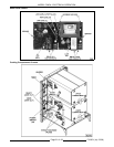

MODEL C24EA - ELECTRICAL OPERATION
F35453 (July 2008)Page 55 of 68
2) HL LED off. High level (HL) coil de-energized by ILR-2 contacts opening.
a. WLC (HL) contacts open. Slow fill solenoid (4SOL) de-energized.
2. Timers reach zero (Upper & Lower Compartments).
A. Upper compartment - Timer contacts 11/13 and 21/23 open.
1) LED 6 off. Upper cavity relay (K8) de-energized. K8-3/5 contacts return to N.O. condition.
a. LED 8 off. Cavity condensate solenoid (2SOL) de-energized.
b. Heat exchanger relay (K10) de-energized. K10- 3/5 contacts return to N.O. condition and heat
exchanger element (1) de-energized.
c. K8-6/4 contacts return to N.O. condition.
2) Cook light (2LT) (red) off. Steam solenoid de-energized.
3) Timer motor de-energized.
B. Lower compartment - Timer contacts 11/13 and 21/23 open.
1) LED 7 off. Lower cavity relay (K9) de-energized. K9-3/5 contacts return to N.O. condition.
a. LED 8 off. With upper compartment timer expired, cavity condensate solenoid (2SOL) and
heat exchanger relay (K10) are de-energized. K8-3/5 contacts are open.
a) K10-3/5 contacts open and heat exchanger element (1) de-energized.
b. Heat exchanger relay (K12) de-energized. K8-6/4 and K9-3/5 contacts return to N.O. condition.
Heat exchanger element (2) de-energized.
2) Cook light (2LT) (red) off. Steam solenoid de-energized.
3) Timer motor de-energized.
C. Buzzer energized through timer N.O. contacts 11/14 (upper or lower cooking compartment timer).
1) Buzzer remains energized until: Timer turned to OFF; New time or CONSTANT steam selected; Or
power switch turned off.
Turning Steamer Off
1. Timers off (upper and lower cooking compartments).
2. Power switch (1S) turned off.
A. Power light (3LT) (amber) on control panel off.
3. LED 9 Lit. Drain (TDR) energized thru K4-6/2 N.C. contacts. 120VAC output from load terminal on drain
(TDR) for 3 minute (default) drain cycle time.
A. LED 10 Lit. Drain relay (K3) energized.
1) K3-3/5 N.O. contacts close. HL LED off; LLCO LED lit. WLC remains powered.
2) K3-1/5 N.C. contacts open. Prevents possible short circuit in the event power switch is turned on.
3) K3-6/2 N.C. contacts open. Removes power from heating circuit and compartment controls. Ready
lights (1LT) (green) are off for the upper and lower compartments.
B. Drain transformer (2T) powered (120/24VAC).
1) 24VAC drain valve energized. Valve opens and steam generator begins draining.
4. Drain water temperature above 130°F. Condensate thermostat (1TAS) contacts close (N.O. contacts - close
on temperature rise).
A. Drain cooling valve (1SOL) energized until drain water temperature is below 120°F.
5. Pressure switch (2PAS) N.C. contacts return to closed condition when steam generator pressure drops below
4" W.C.
A. LED 12 lit. Vacuum relief solenoid (5SOL) energized. Solenoid valve must be open to provide air vent
and allow steam generator to drain.