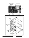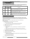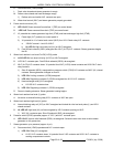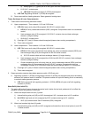
MODEL C24EA - ELECTRICAL OPERATION
F35453 (July 2008)Page 47 of 68
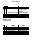
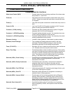
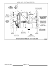
Solenoid, Delime Valve .................. Controlled by delime relay K7 and drain circuit operation. When
energized by 24VAC, valve opens to allow deliming of the heat
exchanger and elements during a delime cycle.
Switch (1PAS), Pressure ................. Pressure cut-out protection. Range is between 4.5 to 4.7 psi.
Removes power from heating circuit if steam generator pressure
rises above the pressure switch setting.
Switch (2PAS), Pressure ................. Vacuum and fill pressure sensing for the steam generator.
When generator is draining, provides power to vacuum relief
solenoid to prevent a vacuum from developing in the steamer.
When generator is initially heating and pressurizes above 4"
W.C. the pressure switch opens to remove power from vacuum
relief solenoid to allow generator to reach operating pressure.
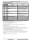
Thermostat (1TAS), Condensate ........... Monitors temperature of water entering the facility drain system.
Controls the drain cooling solenoid during cooking operation and
drain cycle (130EF close).
High-Limit (2TAS), Steam Generator ....... Protects steam generator heating elements from over-
temperatures. Capillary tube device (257EF cut-out; 246°F auto
reset).
High-Limit (3TAS), Heat Exchanger ........ Protects heat exchanger elements from over-temperatures.
Surface mount device (500EF cut-out; auto reset 450°F).
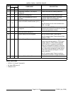
Transformer (1T), Main .................. Step down transformer from line voltage to 120VAC control
circuit voltage.
Relay, Heat Exchanger (K10) ............. Connects heat exchanger element (1) to power. On constantly
whenever one or both cooking compartment timers are set.
Relay, Heat Exchanger (K12) ............. Connects heat exchanger element (2) to power. On constantly
whenever both cooking compartment timers are set.
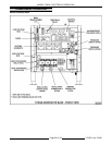
Control Board .......................... Controls steam generator operation, draining and deliming
functions. Provides a central location for wire harness
connections and power transfer thru board relays K1 thru K9
and K11 to the steamer controls. Houses 18 LED's for visual
operation status and troubleshooting.
NOTE: The relay’s below are mounted on the control board and are individually replaceable.
Relay (K1) ............................. Controlled by pressure switch (1PAS). K1 relay is energized
when the pressure switch N.O. contacts close.
Relay (K2), Delime ...................... Controlled by delime circuit. K2 relay is energized when delime
switch is turned on (momentary).
Relay (K3), Drain Relay .................. Controlled by drain time delay relay. K3 relay is powered when
power switch is turned off and drain time delay is energized for
the drain cycle.
Relay (K4), Delime ...................... Controlled by delime circuit. K4 relay is energized when delime
switch is turned on (momentary).
Relay (K5) ............................. Controlled by delime circuit. When delime valve is energized,
the delime valve end switch contacts close and K5 relay is
energized.
Relay (K6) ............................. Controlled by delime switch. K6 relay is energized when delime
switch is turned to CANCEL to stop a delime cycle.
Relay (K7) ............................. Controlled by delime circuit. K7 relay is energized when delime
time delay relay 1 is energized during delime cycle.
Relay (K8), Cavity ...................... Controlled by upper cooking compartment timer. When timer is
set, K8 relay is energized and K8- 5/3 contacts close to provide
power to cavity condensate solenoid and heat exchanger relay
(K10). Heat exchanger element (1) energized.


