


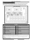
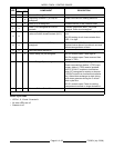

MODEL C24EA - CONTROL BOARD
F35453 (July 2008)Page 41 of 68
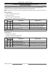
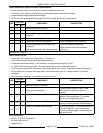
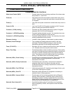
LED
STATUS
COMPONENT DESCRIPTION
ON OFF
1 X Same as Starting Conditions
3X
Regulating contactor 1 (2CON) de-
energized.
Power removed from heating elements.
5 X Relay (K1) de-energized. Pressure switch (1PAS) contacts close.
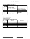
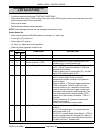
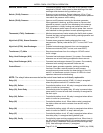
9X
Drain (TDR) energized thru K4-6/2
contacts.
120VAC output from drain (TDR) load
terminal. Drain circuit energized.
11 X
Drain relay (K5) is energized thru delime
valve end switch closed contacts (N.O.).
K5-6/4 contacts close and delime light (4LT)
is lit.
K5-5/3 latching circuit close contacts allow
LED 11 to light.
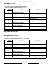
12 X
Vacuum relief solenoid (5SOL)
energized.
Pressure switch (2PAS) contacts close.
Solenoid valve opens to provide air vent and
allow steam generator to drain.
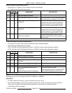
13 X Same as Delime Switch On
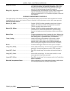
14 X Delime Relay (K4) de-energized. K4-5/3 contacts open. Power light off.
K4-6/4 contacts open. Power removed from
delime 2 (TDR).
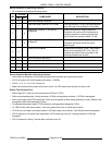
15 X Delime Relay (K2) de-energized. K2-6/4 contacts open. Delime light off.
Power removed from delime 1 (TDR) input
trigger, delime 1 (TDR) remains powered
thru K7-5/3 N.O. contacts to hold delime
relay (K7) energized for a delay on dropout
(120VAC output from load terminal remains
on). Allows heat exchanger to drain (along
with steam generator during the 3 minute
drain cycle time.
K2-5/1 contacts open. Power to cooking
compartment controls no longer locked out.
17 X Same as Delime Switch On
All other LED's are off.
Delime Cycle Ends
• LED's 1, 9, 12 and 13 remain lit.
• All other LED's are off.
• Steamer is off.