


YORK INTERNATIONAL
46
C
B
438
C
B
43
2321
2235
25
229
51
25 TYP.
CONTROL ENTRY
(8) 22 DIA. HOLES
57
127
89
432
25 TYP.
CONTROL ENTRY
(7) 13 CONDUIT K.O.'S
3 SPA. @ 127
44
127
83
229
432
178
POWER ENTRY
(8) 38,51,64 CONDUIT K.O.'S
51
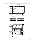
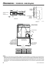
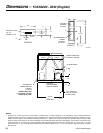
CONTROL CENTER
MICRO-COMPUTER
OPTIONS PANEL
CONNECTION)
49 (EDGE OF
UNIT TO COOLER
VIEW A-A
VIEW C-CVIEW B-B
POWER: MULTIPLE POINT WITH TERMINAL BLOCKS
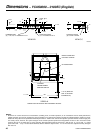
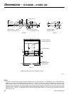
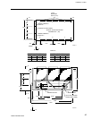
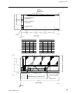
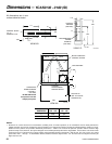
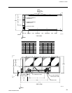
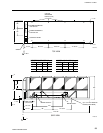
Dimensions – YCAS0110 – 0120EC (SI)
NOTES:
1. Placement on a level surface free of obstructions (including snow, for winter operation) or air recirculation ensures rated performance,
reliable operation and ease of maintenance. Site restrictions may compromise minimum clearances indicated below, resulting in unpre-
dictable air flow patterns and possible diminished performance. YORK’s unit controls will optimize operation without nuisance high
pressure safety cutout; however, the system designer must consider potential performance degradation. Access to the unit control center
assumes the unit is no higher than on spring isolators. Recommended minimum clearances: Side to wall - 2m; rear to wall - 2m; control
panel end to wall - 1.2m; top - no obstructions allowed; distance between adjacent units - 3m. No more than one adjacent wall may be
higher than the unit.
LD05208