


YORK INTERNATIONAL
FORM 201.18-EG1
99
6. Display Data: Chiller liquid return and leaving tem-
peratures, ambient, lead compressor identifica-
tion and lead/lag delay, clock and schedule, (vari-
able) out of range, remote input indication, chilled
liquid reset setpoint, leaving liquid pull-down rate
setpoint, leaving liquid error (deviation from set-
point), and history data for last six shutdown faults.
Compressor suction, discharge, and oil pressures
and temperatures, suction and discharge super-
heats, percent of full-load motor current, operat-
ing hours, starts, and anti-recycle timer status.
Status Messages for manual override, unit switch
off, compressor run, run permissive, remote con-
trolled shut down, no cooling load, daily/holiday
shut down, anti-recycle/anti-coincident timer, high
pressure low suction temperature limit.
7. System Safeties: Shall cause individual compres-
sor systems to perform auto-reset shut down;
manual reset required after the third trip in 90
minutes. Includes: high discharge pressure or
temperature, low suction pressure, high / low
motor current, high pressure switch, high / low
differential oil pressure, high oil temperature, and
motor protector. Compressor motor protector shall
protect against damage due to: low or high input
current, phase reversal (reverse rotation), current
unbalance, phase loss, thermal overload of wind-
ings, and low voltage.
8. Unit Safeties: Shall be automatic reset and cause
compressors to shut down if: high or low ambi-
ent, low leaving chilled liquid temperature, under
voltage, and flow switch operation. Contractor
shall provide flow switch and wiring per chiller
manufacturer requirements.
9. Alarm Contacts: High or low ambient, low leaving
chilled liquid temperature, low voltage, low bat-
tery, and (per compressor circuit): high discharge
pressure or temperature, low suction pressure,
low or high motor current, low or high differential
oil pressure, and high oil temperature.
E. Manufacturer shall provide any controls not listed
above, necessary for automatic chiller operation.
Mechanical Contractor shall provide field control wir-
ing necessary to interface sensors to the chiller con-
trol system.
2.06 POWER CONNECTION and DISTRIBUTION
A. Power Panels:
1. NEMA 3R/12 (IP55) rain/dust tight, powder
painted steel cabinets with hinged, latched, and
gasket sealed outer doors equipped with wind
struts for safer servicing. Provide main power
connection(s), compressor and fan motor start
contactors, current overloads, and factory wiring.
2. Field power supply wiring connections shall be to
a single power center on the chiller, shall be 3
phase of scheduled voltage, and shall connect to
terminal blocks per each of the two motor control
panels. Separate disconnecting means and/or ex-
ternal branch circuit protection (by Contractor) re-
quired per applicable local or national codes.
3. Provide two electrically separate, adjacent motor
control center cabinets, with independent doors
and separated by a steel panel, for compressor
and fan motor power distribution components.
B. Exposed compressor and fan motor power wiring
shall be routed through liquid tight conduit.
2.07 ACCESSORIES and OPTIONS
Some accessories and options supercede standard
product features. Your YORK representative will be
pleased to provide assistance.
A. Microprocessor controlled, Factory installed Wye-
Delta compressor motor starters for reduced com-
pressor inrush start current. Two-compressor ma-
chines with Single-Point Power connection and
equipped with Star-Delta compressor motor start
must also include factory provided circuit breakers
in each motor control center. All 3 & 4 compressor
machines equipped with Star-Delta compressor mo-
tor start must also include factory provided circuit
breakers in each motor control center.
B. Power Supply Connections:
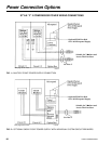
1. Two Compressor Machines –
a. Multiple Point with Individual System Circuit
Breakers or Non-Fused Disconnect Switches:
Two Field provided branch circuits shall con-
nect to Individual System Circuit Breakers or
Non-Fused Disconnects per compressor on
each of the two motor control centers, with
lockable external handles on doors in compli-
ance with Article 440-14 of the N.E.C.
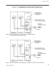
b. Single-Point Terminal Block or Non-fused Dis-
connect Switch: Field provided branch circuit
shall connect to single-point Terminal Block
or Non-Fused Disconnect with lockable exter-
nal handle in compliance with N.E.C. Article
440-14, with Factory provided interconnect-
ing wiring to (optional Individual System Cir-
cuit Breakers, and) compressor motor start
components in each of two motor control cen-
ter cabinets.
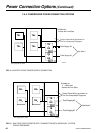
c. Single-Point Circuit Breaker: Field provided
branch circuit shall connect to Single-Point Cir-
cuit Breaker with Lockable External Handle
(in compliance with Article 440-14 of N.E.C.)