Installation, cont’d
SGS 408 Switcher • Installation2-2
Installation
Rear Panel Connectors
Front panel features are shown on page 3-2.
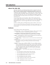
Figure 2-1 — SGS 408 rear panel
1
AC power connector — One standard AC power connector attaches the
switcher to any power source from 100VAC to 240VAC, operating at 50 or
60 Hz.
2
Input connectors — Eight sets of five BNC female connectors for
component video, RGsB, RGBS, and RGBHV input devices.
3
Output BNC connectors — Two sets of five BNC female connectors for
output to RGBS or RGBHV devices. One set of connectors is dedicated to
the program image, and one set to the preview image.
4
RCP port — One 4-pin female XLR connector that allows you to attach the
RCP 1000 remote control panel to the SGS 408. Refer to the RCP 1000 User’s
Manual for more information.
5
RS-232 connector — One 9-pin D female connector that allows you to
attach an ECP 1000 event control panel, a computer, or controlling device
for remote control of the switcher.
6
DVI output connector (optional) — One DVI connector that allows you to
attach the switcher to a DVI output device. The connector is dedicated to
the program image.
7
Output 15-pin HD connectors — Two connectors for output to RGBS or
RGBHV devices. One connector is dedicated to the program image, and
one to the preview image. The connectors receive the same signals as the
output BNC connectors.
Installation
To install the switcher, follow these general steps:
1
If desired, mount the switcher in a rack (see “Mounting the switcher” on
page 2-3). Otherwise, install the rubber feet (see “Tabletop/desktop
placement” on page 2-4).
2
Turn off power to the input and output devices, and unplug the power
cables from them.
3
Attach the input and output devices to the switcher. See “Cabling” on page
2-4.
100
-
240
50/60 Hz
1.2A MAX.
R/R-Y
1
G/Y
B/B-Y
H/HV
V
R/R-Y
2
G/Y
B/B-Y
H/HV
V
R/R-Y
3
G/Y
B/B-Y
H/HV
V
R/R-Y
INPUTS
4
G/Y
B/B-Y
H/HV
V
R/R-Y
5
G/Y
B/B-Y
H/HV
V
R/R-Y
6
G/Y
B/B-Y
H/HV
V
R/R-Y
7
G/Y
B/B-Y
H/HV
V
R/R-Y
8
G/Y
B/B-Y
H/HV
V
R
PROGRAM
OUTPUTS
PROGRAM
PREVIEW
REMOTE
PROGRAM
DVI OUT
RCP
G
B
H/HV
V
R
PREVIEW
G
B
H/HV
V
1 2
3 4 5 6
7