2-3SGS 408 Switcher • Installation
4
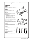
If desired, attach a computer or other control device to the RS-232 connector.
5
If desired, attach an RCP 1000 remote control panel. See “Attaching an
RCP 1000” on page 2-6.
6
If desired, attach an ECP 1000 event control panel. See “Attaching an
ECP 1000” on page 2-6.
7
Plug the switcher, input devices, and output devices into a grounded AC
source.
8
Turn on the input and output devices.
9
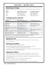
Use the LCD menu screens to configure the switcher. See “Configuring the
SGS 408” on page 3-4.
10
The image from each input device should appear on the output devices, and
you should be able to switch from one input device to another. If this does
not happen, double check steps 3 and 4 and make adjustments as needed. See
chapter 5 for additional assistance.
Mounting the switcher
The switcher ships with four uninstalled rubber feet. If you are going to rack
mount the switcher, do so before cabling it, and do not install the rubber feet. If
you are not rack mounting the switcher, skip to “Tabletop/desktop mounting”
on the following page.
Rack mounting
To rack mount the switcher, use two screws on each end of the switcher to attach
the switcher to the rack. See figure 2-2.
Figure 2-2 — Mounting the switcher
PROGRAM
FREEZE
BLACK
1
2
3
4
5
6 7 8
CUT TAKE
PROGRAM
PREVIEW
OUTPUT RATE
EFFECT
TRANSITION
SGS 408
SEAMLESS GRAPHIC
SWITCHER
INPUT
1 2
3 4
TRANSITIONS
EFFECT
S
RCP COMMUNICATION
PREVIEW
FREEZE BLACK 1
2
3 4
5 6
7
8
Tx
Rx