Installation, cont’d
SGS 408 Switcher • Installation2-8
Making an RCP comm cable
Use the following guidelines to make an RCP cable:
• At one end, attach a female 4-pin XLR connector.
• At the other end, attach a male 4-pin XLR connector.
• Connect pins straight through.
• Use at least 18 gauge wire paired with 20 gauge wire for power (pin 1), 18
gauge wire paired with 20 gauge wire for ground (pin 4), and 20 gauge
twisted-pair wire for communications (attach one pair to pin 3 and the
other pair to pin 4).
• The cable can be up to 1000 feet (304.8 meters) long.
• Power is supplied by the SGS 408.
DVI cable pinouts
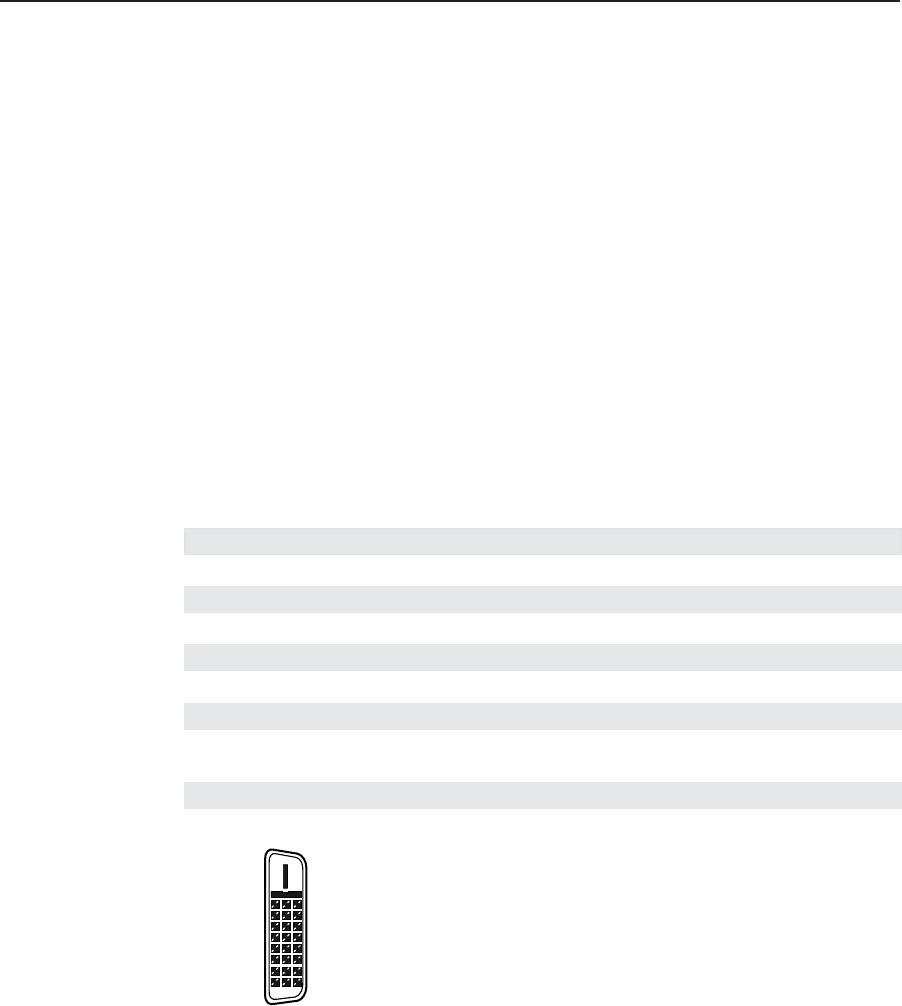
The optional DVI connector (figure 2-10) uses the following pinouts:
Pin Signal Pin Signal Pin Signal
1 TMDS data 2– 9 TMDS data 1+ 17 TMDS data 0–
2 TMDS data 2+ 10 TMDS data 1+ 18 TMDS data 0+
3 TMDS data 2/4 shield 11 TMDS data 1/3 shield 19 TMDS data 0/5 shield
4 TMDS data 4– 12 TMDS data 3– 20 TMDS data 5–
5 TMDS data 4+ 13 TMDS data 3+ 21 TMDS data 5+
6 DDC clock 14 +5 V power 22 TMDS clock shield
7 DDC data 15 Ground (+5 V, analog 23 TMDS clock +
H/V sync
8 Analog vertical sync 16 Hot plug detect 24 TMDS clock–
Figure 2-10 — DVI connector
1
9
8
17
24