B-3SGS 408 Switcher • Reference Information
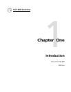
Figure B-2 — Installing the DVI connector option
2. Insert the DVI connector through the hole that was created in the rear panel
in step 1.
3. Carefully align the DVI circuit card 50-pin connector with socket J3 on the
SGS 408 circuit board. With the pins aligned, press down gently on the DVI
circuit card. Check the alignment of the DVI circuit card and socket J3.
4. Reinstall the cover of the SGS 408.
5. Attach the power cord to the SGS 408 and to the AC power source. Make
sure the SGS 408 is working correctly.
6. If the SGS 408 is rack mounted, remove the power cable from the SGS 408
and reattach the SGS 408 to the rack. Reconnect the power cord and the
input and output cables.
Replacing the AC fuse
If the switcher does not power on, and the AC power source is functioning
correctly, the AC fuse may be blown. The fuse is located on the internal power
supply which is located on the right side of the SGS, as viewed from the front (see
figure B-3).
Be sure to remove the power cable from the switcher before attempting to
replace the fuse. Replace the fuse only with a 5 x 20 mm, 5A/250V fast
blow fuse.
1. Remove the cover of the switcher. See “Internal access” on page B-2.
2. Locate the fuse on the power supply, and remove it from its retaining clips
(see figure B-3).
After removing the DVI connector cover,
insert the DVI connector through the
opening in the chassis and press
the circuit card evenly into the socket.