


Chapter 1 Getting Started
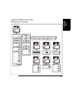
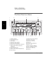
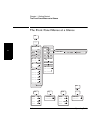
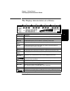
The Rear Panel at a Glance
Operating Guide 1-7
1
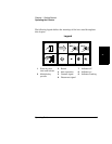
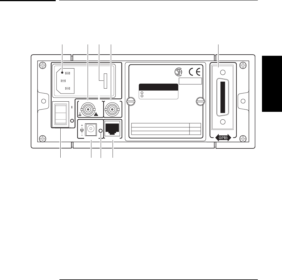
The Rear Panel at a Glance
1 AC Input/Power module (Senses
incoming voltage and adjusts
automatically)
2 External Reference connector (BNC)
1, 2, 5, or 10 MHz Input
10 MHz Output
3 Fuse Holder (behind door)
4 Auxiliary connector (reserved)*
5 Battery compartment (optional) or cover plate
6 GPIB (IEEE-488.1) Interface connector
7 RS-232 Interface connector (RJ12)
8 Main AC Power On indicator
9 EXT DC power-input connector (functional only
when Battery option is installed)
10 Main ~ Power switch
* The Auxiliary connector is not installed on standard production units.
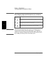
11 TO 18 VDC
EXT DC
Reference 10 MHz
In
or
Out
Auxillary
RS-232
Main ~ Power
1
10 9 7
2 43 6
5
8
WARNING:
To avold electric shock,
do not remove covers.
No user-serviceable parts inside.
Refer all servicing to qualified personnel.
OPTIONS
001 Oven Time Base
002 Battery
This unit must be earth grounded.
Made in U.S.A.
with domestic and foreign content
ISM 1-A
100 – 130 VAC, 50/60/400 Hz 75 VA
220 – 240 VAC, 50/60 Hz 75 VA 250 V
FUSE
1.0 A T
AC POWER