


-21-
Revision 4/F3576 © Moffat Ltd, December 2004
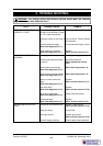
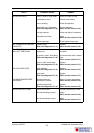
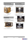
6.1.3 FAN DOESN’T OPERATE
Fan motor faulty
Check the supply voltage across motor termi-
nals. If there is no voltage then check the
electrical connections of wiring.
If voltage is correct then check the oven fan
for free rotation. Remove any obstruction.
If fan is free to spin and the voltage at motor
terminals is correct, then the motor is faulty—
replace.
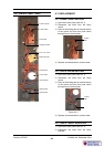
Fan switch faulty
Check that the thermostat has power to
terminal 5 on switch body on the front of the
thermostat when power switch is ON. If no
voltage check wiring. Check that terminal P5
has power switched to it when the thermostat
is turned on. If no power to P5 then switch is
faulty and thermostat complete with switch
needs to be replaced.
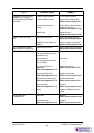
No power to thermostat
Check voltage to terminal 1 on oven
thermostat. If there is no voltage then check
voltage through terminal 2 and 3 on roast n
hold switch. If there is no voltage to terminal
2 then check wiring. If there is voltage to ter-
minal 2, but no voltage to terminal 3 (and the
roast n hold switch is not turned on) then
switch is faulty—replace.
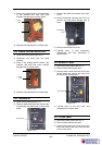
Thermostat faulty
Set thermostat to 200°C. Check the voltage
out of terminal 2 on the thermostat. If there is
no voltage then the thermostat is faulty—
replace.
If the voltage is correct and the heating light is
on then check all wiring to ignition box.
Gas valve faulty
In all cases it must first be established that the
gas supply is on, and that the supply
pressure is correct (refer to specifications
section)
If pressure is correct then with thermostat
turned on check voltage at connections to the
gas valve solenoid.
If voltage is correct when thermostat is on,
and gas valve is not opening, then the gas
valve is faulty - replace.
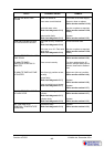
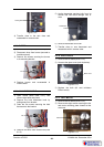
Check correct supply voltage on ignition box
wires connecting to terminal 1 of the hold
thermostat, and a control panel neutral wire.
This confirms that the thermostat circuit is
supplying the correct voltage to the ignition
box connection wires. To confirm actual
voltage to ignition box, the 6-way connector
on the ignition box requires removal to check
actual voltage in ends of 6 way connector for
these two wires.
If voltage is ok, but no spark is generated,
check that all wiring at ignition box has good
connections.
Ensure that the ignition box has earth/ground
connection, and that appliance has earth/
ground at supply, and supply is earthed.
If all connections are ok, and no ignition
sequence operating, then ignition box is faulty
- replace.
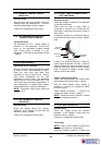
If ignition box generates spark, but burner
doesn’t ignite, or if burner ignites but doesn’t
stay alight, firstly check correct electrode
assembly operation. Refer fault diagnosis
6.1.2 - Burner Ignition Spark Not Working.
If all checks are correct, but burner fails to
stay alight then ignition box is faulty - replace.
NOTE:
Correct flame sensing current can be
checked by inserting a multi-meter capable of
measuring micro-amps in series with flame
rectification rod connection to ignition box.
With power off, disconnect flame rectification
rod connection to ignition box and connect
multimeter between flame rectification rod
lead and ignition box terminal. Turn on power
and thermostat. With burner running a current
of no less than that specified below should be
read.
All Models 1.0 micro Amps
If no current reading, or less than specified,
re-check electrode settings, gas pressure, gas
type etc, and if still not correct, ignition box
requires replacement.
If voltage is incorrect, check wiring and
connections to ignition box and refer to
ignition box fault diagnosis.