


-31-
Revision 4/F3576 © Moffat Ltd, December 2004
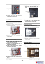
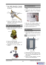
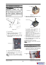
Injection
Nozzle
Units Manufactured up to S/N 275353
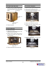
1) Remove right hand side panel (refer
6.2.4).
2) Disconnect the two wires leading to the
gas solenoid.
3) Disconnect main gas supply pipe from
copper connection line to manifold.
4) Loosen pipe clamp at rear of oven and
remove main supply pipe assy.
5) On work bench undo gas solenoid valve
from assembly and replace.
Figure 6.3.25
Solenoid Valve
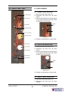
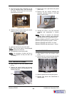
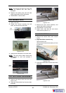
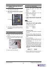
1) Ensure water supply is turned off.
2) Remove the water injection nozzle from
inside the oven (refer 6.3.19).
3) Remove the water solenoid access panel
at the rear of the oven (4 screws).
6.3.20 WATER SOLENOID VALVE
1) Remove the fan baffle (refer 6.2.2).
2) Unscrew the water injection nozzle.
3) Clean or replace nozzle, and reassemble
in reverse order.
6.3.19 WATER INJECTION NOZZLE
Figure 6.3.26
Figure 6.3.27
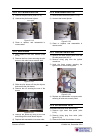
4) Remove the wires from the solenoid, and
disconnect the mains water connection.
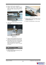
5) Remove the two screws securing the
solenoid bracket to the oven rear, and
remove the valve assembly.
Figure 6.3.28
Water
solenoid
access panel
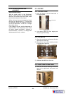
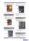
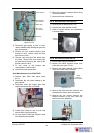
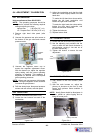
4) Disconnect gas supply at rear of oven,
remove saddle clamp holding the gas inlet
pipe (two screws).
5) Remove the four screws securing valve
bracket to oven, remove valve and inlet
pipe from the oven.
6) Unscrew gas inlet pipe and elbow from
the valve. Remove the four screws (two
top and bottom) securing the valve to the
bracket, remove valve.
7) Fit new valve to the bracket and
re-assemble in reverse order.
8) Leak test all new connections.
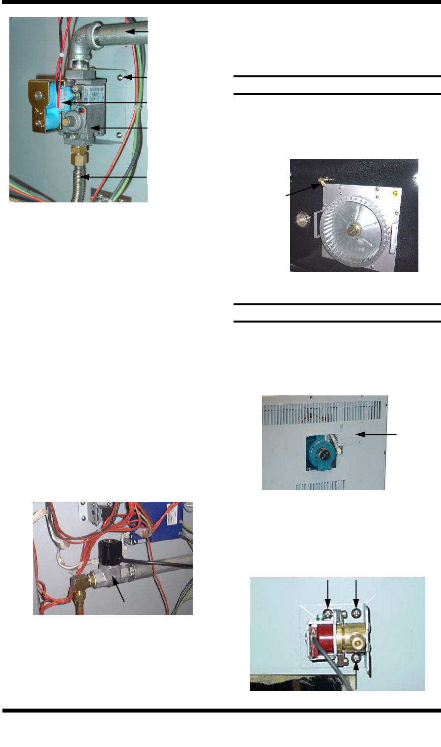
Figure 6.3.24
Gas Inlet Pipe
Wiring Plug
Flex-tube
Gas Valve
(four screws)
Valve Bracket
(four screws)
6) Refit and reconnect solenoid wires using
reverse procedure.
7) Leak test all new connections.