-30-
Revision 4/F3576 © Moffat Ltd, December 2004
Pilot Injector
1) Remove the side service panel from the
RH side panel (refer 6.2.3).
2) Remove wiring plug from the ignition
control box.
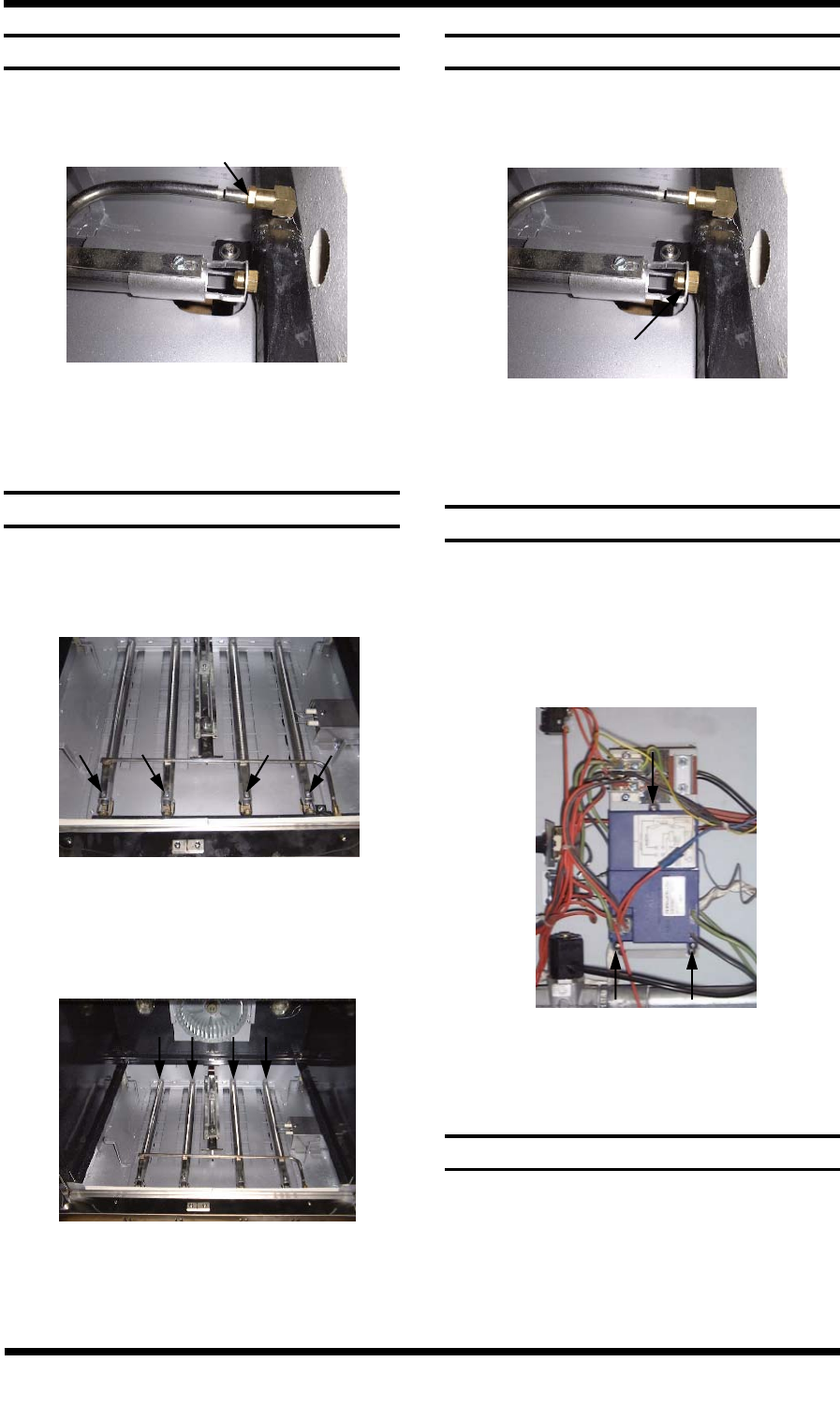
3) Undo the three screws securing the
ignition box to the mounting panel.
1) Gain access to the oven burners (refer
6.2.6).
2) Remove the four screws securing the pilot
burner to the main burner aeration slide.
6.3.15 MAIN BURNER
Figure 6.3.20
3) Slide the pilot burner off the pilot injector
and remove the pilot burner.
4) Remove the nut securing the rear of the
burner.
1) Remove the pilot burner (refer 6.3.13).
2) Unscrew the pilot burner injector.
6.3.14 PILOT BURNER INJECTOR
Figure 6.3.19
3) Clean or replace, and reassemble in
reverse order.
5) Remove the burner by lifting at the rear
and sliding off the main burner injector.
6) Replace and reassemble in reverse order.
Figure 6.3.21
1) Remove the main burner (refer 6.3.15).
2) Unscrew the burner injector.
6.3.16 MAIN BURNER INJECTOR
Figure 6.3.22
3) Clean or replace, and reassemble in
reverse order.
Burner Injector
6.3.17 IGNITION CONTROL BOX
Three screws
Figure 6.3.23
4) Replace and reassemble in reverse order,
ensuring all wires are correctly fitted.
6.3.18 GAS SOLENOID VALVE
Units Manufactured from S/N 275353.
1) Remove right hand side panel (refer
6.2.4).
2) Remove wiring plug from valve (refer
figure 6.3.24).
3) Remove flexi-tube from bottom of valve.


