


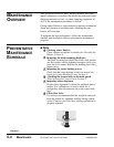
B-LOC Corporation 26 Gilbert Street Monroe, NY 10950 For technical assistance, please call 1-800-865-7756
INSTALLATION AND REMOVAL INSTRUCTIONS FOR
B-LOC™ LOCKING ASSEMBLY SERIES B112
Thank you for purchasing a B-LOC™ Keyless Frictional Locking Device.
B-LOC™ keyless connectors provide a high capacity, zero-backlash
shaft/hub or coupling connection by means of a mechanical interference
fit. Please follow these INSTALLATION AND REMOVAL INSTRUCTIONS
carefully to ensure proper performance of this B-LOC™ unit.
! WARNING !
When installing or removing B-LOC™ products, always adhere to the following
safety standards:
1. Be sure that all power switches are locked out before installing or removing
B-LOC™ products.
2. Eye protection is required when installing or removing B-LOC™ products
- please wear safety glasses and protective clothing.
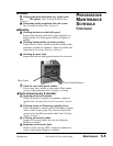
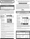
LOCKING SCREW SIZES AND SPECIFIED TIGHTENING TORQUE M
A
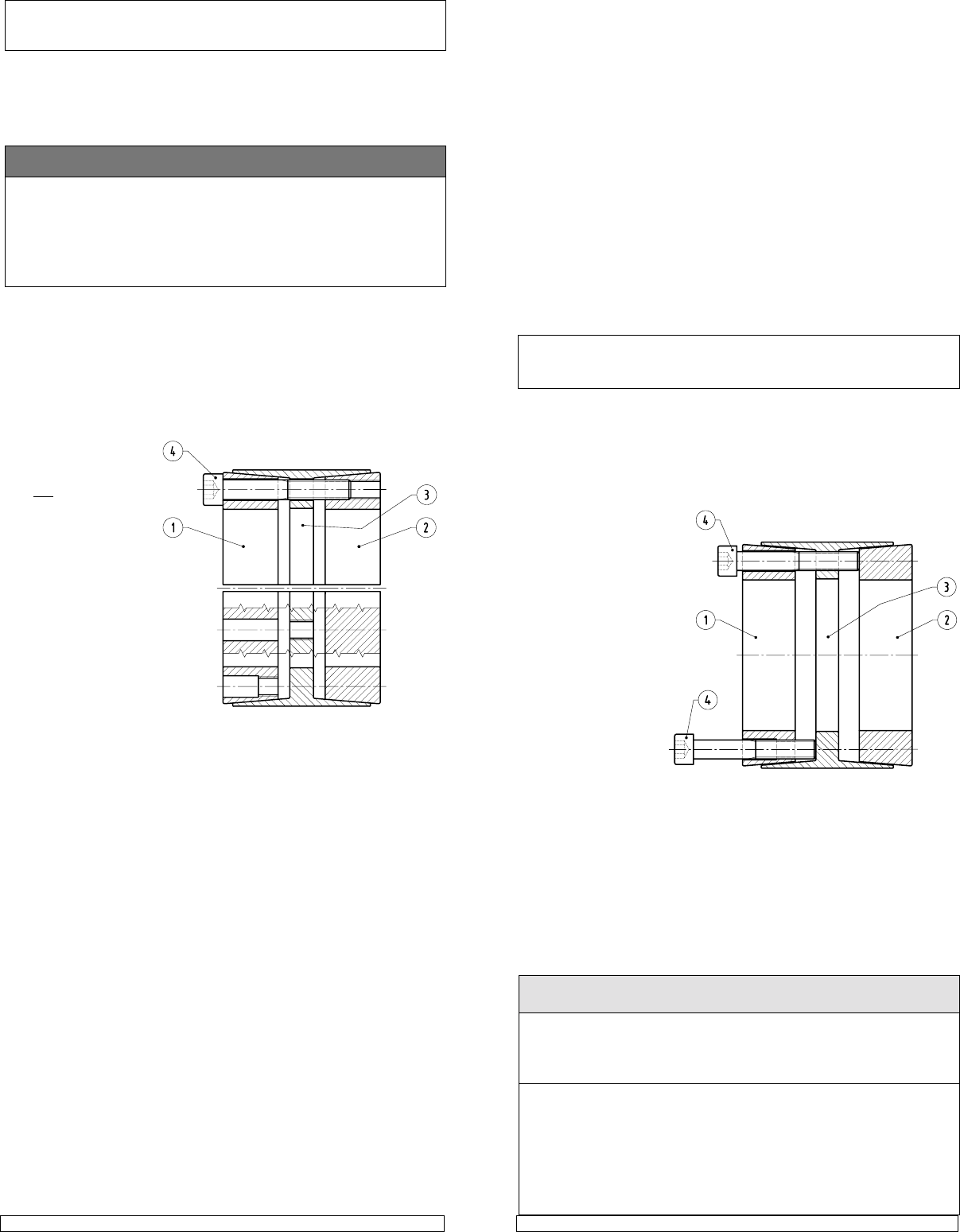
B112 LOCKING ASSEMBLY
Figure 1
25 x 55 to 35 x 60 1 to 1-7/16 12 M 6 5
40 x 75 to 65 x 95 1-1/2 to 2-9/16 30 M 8 6
70 x 110 to 90 x 130 2-5/8 to 3-5/8 60 M10 8
100 x 145 to 120 x 165 3-3/4 to 4-3/4 105 M12 10
130 x 180 to 160 x 210 4-15/16 to 6 166 M14 12
170 x 225 to 260 x 325 6-7/16 to 8 257 M16 14
280 x 355 to 340 x 425 500 M20 17
360 x 455 to 600 x 695 675 M22 17
Metric Series
INSTINST
INSTINST
INST
ALLAALLA
ALLAALLA
ALLA
TIONTION
TIONTION
TION
(Refer to Figures 1 and 2)
B-LOC™ Locking Assemblies are supplied lightly oiled and ready for installa-
tion. When reinstalling a used unit, make sure that all slits are aligned and
that front and rear clamp collars are not reversed (when assembled correctly
there are no holes or threads behind taps in clamp collar Item 1, and no threads
behind taps in center collar Item 3). The frictional torque capacity of these
devices is based on a coefficient of friction of 0.12 for lightly oiled screw,
taper, shaft and bore
contact areas.
Therefore, it is impor-
tant
not to use Molyb-
denum Disulfide (e.g.,
Molykote, Never-Seeze
or similar lubricants) in
any Locking Assembly
installation.
1. Make sure that lock-
ing screw, taper,
shaft and bore con-
tact areas are clean
and lightly oiled and
that all collar slits are
aligned.
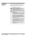
2. Loosen all locking
screws by a minimum of four (4) turns and transfer at least two (2) screws
to push-off threads in clamp collar Item 1 to disengage this part from
center collar Item 3. Similarly, transfer at least two (2) screws to push-off
threads in center collar Item 3 to disengage this part from clamp collar
Item 2 (see Figure 2).
3. Completed assembly can now be placed on shaft and inserted into hub
bore by pushing against face of collar Item 1 while ensuring that collar
Item 2 is not engaged at tapers during this phase.
4. After placement of Locking Assembly, relocate locking screws used for
separation of collars.
5. Hand tighten connection and confirm that clamp collar Item 1 is parallel
with face of part to be attached to shaft and/or with the front facing edge of
center collar Item 3.
6. Use torque wrench and set it approximately 5% higher than specified tight-
ening torque M
A
. Tighten locking screws in either a clockwise or counter-
clockwise sequence (it is not necessary to tighten in a diametrically oppo-
site pattern), using only 1/4 (i.e., 90°) turns for several passes until 1/4
turns can no longer be achieved.
7. Continue to apply overtorque for 1 to 2 more passes. This is required to
compensate for a system-related relaxation of locking screws since
tightening of a given screw will always relax adjacent screws. Without
overtorquing, an infinite number of passes would be needed to reach
specified tightening torque.
8. Reset torque wrench to specified torque (M
A
) and check all locking screws.
No screw should turn at this point, otherwise repeat Step 7 for 1 or 2 more
passes. It is not necessary to re-check tightening torque after equipment
has been in operation.
Figure 2
NOTE: In installations subjected to extreme corrosion, the slits in clamp
collars Item 1 and Item 2, as well as in center collars, should be
sealed with a suitable caulking compound or equivalent. Likewise,
push-off threads should also be protected from corrosion.
INSTINST
INSTINST
INST
ALLAALLA
ALLAALLA
ALLA
TION OF TION OF
TION OF TION OF
TION OF
B-LB-L
B-LB-L
B-L
OC™OC™
OC™OC™
OC™
L L
L L
L
OCKINGOCKING
OCKINGOCKING
OCKING
ASSEMBLIES OASSEMBLIES O
ASSEMBLIES OASSEMBLIES O
ASSEMBLIES O
VER SHAFT KEYWVER SHAFT KEYW
VER SHAFT KEYWVER SHAFT KEYW
VER SHAFT KEYW
AA
AA
A
YY
YY
Y
SS
SS
S
The Locking Assembly should be positioned so that slits in Locking Assembly
collars that contact the shaft are located approximately opposite the keyway.
In addition, a locking screw should be centered directly over the keyway.
When tightening locking screws, it is important to follow the installation proce-
dure outlined above, which specifies equal 1/4 turns of each locking screw.
Failure to follow these instructions could result in excessive tightening of the
screw over the keyway, possibly causing permanent deformation of the Lock-
ing Assembly collars. Even after 1/4 turns can no longer be achieved, it is
important to continue to use equal turning angles for every screw until the
specified tightening torque is reached.
REMOREMO
REMOREMO
REMO
VV
VV
V
ALAL
ALAL
AL
(Refer to Figure 2)
Prior to initiating the following removal procedure, check to ensure that
no torque or thrust loads are acting on the Locking Assembly, shaft or
any mounted components.
IMPORTANT! Make sure ends of locking screws used for removal are
ground flat and are slightly chamfered to prevent damage
to screw and collar threads during push-off.
1. Check to ensure that axial movement of clamp collars - necessary for
release of connection - is not restricted. Likewise, ensure that push-off
threads are in good
condition.
2. Remove all locking
screws. Transfer re-
quired number of
screws into all push-
off threads of clamp
collar Item 1 (see
Figure 2).
3. Release collar Item 1
by progressively tight-
ening all push-off
screws. Typically, the
push-off screws ap-
pear to be completely
tight after just one
pass of tightening
without any notice-
able separation of clamp collars. Although it seems that the screws cannot
be tightened further, several more rounds of torquing in either a clockwise or
counterclockwise sequence will increase the push-off force in the system and
ultimately release part of the front collar. Afterwards, only the screws which
are still tight should be tightened further until complete dismounting is achieved.
Remove clamp collar Item 1.
4. Transfer locking screws used for dismounting of clamp collar Item 1 into
all push-off threads in center collar Item 3 (see Figure 2). Release clamp
collar Item 2 by repeating procedures outlined in Step 3.
Tightening
Torque
M
A
(ft-lbs)
Hex
Key
Size
(mm)
Screw
Size
Inch Series