


42
312028000
B. Carefully install valve with caged O-ring in dispensing valve body.
C. Install spring fitting, knob and lever parts, torsion spring, and spring housing assembly by reversing
removal procedure. Do not tighten hold-down plates securing spring housing at this time.
10. Thoroughly clean RELIEF VALVE (item 9), then screw relief valve into FACEPLATE (item 8).
11. Proceed to Servicing Beater Motor Drive Shaft/Seal Assemblies
.
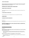
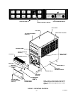
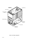
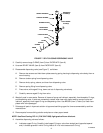
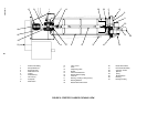
Servicing Freeze Cylinders Drive Shaft/Seal Assemblies.
(see Figure 9)
IMPORTANT: The freeze cylinders drive shaft/seal assemblies must be removed and inspected every
four months. Their shafts and bearings must be inspected and replaced if necessary. All O-Ring seals
must be replaced at this time.
NOTE: Use Dow-Corning DC-111 (P/N 321471000) light grade silicone lubricant.
1. Pull BEATER (item 13) and SCRAPER BLADES (item 2) from freeze cylinder.
2. Using WRENCH (item 11, LOOSE-SHIPPED PARTS), reach into the freeze cylinder and turn the drive
shaft/seal assembly to the right (clockwise) to unlock its four locking tabs from the notches in the freeze
cylinder retainer. Pull the assembly out of the freeze cylinder retainer using the beater as a puller.
3. Remove the coupling end fitting from the shaft by loosening the set screw in the coupling, then slide cou-
pling off the shaft.
4. Remove the lock-ring bearing retainer from the end of the plastic housing.
5. Using a block of wood, tap the drive shaft and both bearings out of the plastic housing.
6. Loosen bearings and remove shaft. Remove two old inner drive shaft O-Ring seals and two outer O-Ring
seals from the plastic housing. Discard the old O-Ring seals.
NOTE: If old lubricant cannot be removed from the plastic housing by washing, use a nylon ‘‘pot and
pan’’ scrubber (3M Company ‘‘Scotchbrite’’, or equivalent) to remove the residue. Do not scrape plastic
housing. Replace any housing that has rough edges in O-Ring sealing areas.
7. Remove old lubricant from the plastic housing with paper towel. DO NOT SCRAPE THE PLASTIC HOUS-
ING. Wash the housing and the back of the freeze cylinder with warm water.
8. Lubricate two new drive shaft O-Ring seals with a generous amount of special light-grade silicone grease,
then install O-Rings inside the plastic housing.
9. Inspect the drive shaft and both bearings. Replace the drive shaft if worn and bearing(s) if found to be
rough.
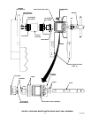
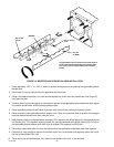
10. Reassemble the drive shaft/seal assembly. Using TOOL, DRIVE/COUPLER ADJUSTMENT GAUGE (item
12), insert “DRIVE” end of adjustment gauge between drive-pin and housing (see Figure 9) to set the shaft
end at 1.542-inches out of the plastic housing. Make sure Allen-Head set screw in each bearing is securely
tightened and properly seated on the shaft flat surface.
11. Install coupling end fitting on end of the drive shaft. Insert “COUPLER” end of the adjustment gauge be-
tween coupling end fitting and the plastic housing. The adjustment gauge in place places the coupling end
fitting 0.750-inch away from the plastic housing. Make sure Allen-Head set screw in the coupling end fitting
is securely tightened and properly seated on the shaft flat surface.
12. Lubricate the two outer O-Ring seals on the outside of the plastic housing with a generous amount of spe-
cial light-grade silicone grease.
13. Reinstall the drive shaft/seal assembly in the freeze cylinder.
14. Push in and turn the drive shaft/seal assembly to the left (counterclockwise) to lock its four locking tabs into
four notches in the freeze cylinder retainer.