


2
312028000
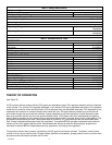
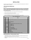
Table 1. Design Data (cont’d)
Refrigeration System:
Compressor Horsepower 2 H.P.
Refrigerant Type And Charge See Unit Nameplate
Ambient Operating Temperature 40° F to 100° F
Electrical Requirements:
Operating Voltage See Unit
Nameplate
Operating Current See Unit
Nameplate
Table 2. Accessories and Tools
ACCESSORIES
Installation kits 1155
Cup Holder 511005000
Cup Holder 511006000
CO
2
Changeover Kit 511035000
GENERIC FLAVOR TABS
Cola 1085
Cherry 1086
Orange 1087
Grape 1088
Lemon-Lime 1089
Strawberry 1090
Banana 1091
SERVICE TOOLS
3-gallon Sanitizing Tank 281884000
Spanner Wrench, Dispensing Valve 322859000
Refractometer, 0-30 Scale 511004000
Wrench, Rear Seal Housing 2899
Tool, Drive/Coupler Adjustment Gauge 3810
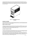
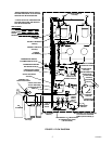
THEORY OF OPERATION
(see Figure 2)
A CO
2
cylinder delivers carbon dioxide (CO
2
) gas to an adjustable primary CO
2
regulator assembly which is attached
to the cylinder. The primary CO
2
regulator assembly in turn delivers CO
2
gas to adjustable secondary CO
2
regulators
inside the Unit and also to two soft drink tanks. CO
2
is delivered from the adjustable secondary CO
2
regulators to the
carbonator tank and also to product-blender tanks inside the Unit. CO
2
gas pressure pushes syrup out of the soft
drink tanks through the syrup sold-out switches, through adjustable syrup flow regulators, through electrically oper-
ated syrup solenoid valves, and on to the product blender tanks. At the same time, plain water passes through the
water pressure regulator and is pumped into the carbonated water tank by the water pump and is carbonated by CO
2
gas pressure also entering the tank. Carbonated water is pushed by CO
2
gas pressure from the carbonated water
tank, through adjustable carbonated water flow regulators, through electrically operated carbonated water solenoid
valves, and on to the product blender tanks. Carbonated water and syrup enter the tanks properly proportioned
(blended) for desired BRIX of dispensed product by adjustment of the syrup flow regulators.
From product blender tanks, product is pushed by the CO
2
gas into the freeze cylinders. The beater in each freeze
cylinder is driven by an electric motor. Scraper blades, attached to the beaters, scrape product from the cylinder walls
as product enters the freeze cylinders and is frozen.