


47 312028000
11. Press applicable ‘‘AUTO BLEND 1’’ or ‘‘AUTO BLEND 2’’ switch to activate the electrically operated car-
bonated water solenoid.
12. When a steady stream of water is flowing from the added length of line, catch carbonated water in a con-
tainer graduated in ounces for exactly 10 seconds. Press applicable ‘‘FILL 1’’ or ‘‘FILL 2’’ switch to deacti-
vate the carbonated water solenoid. In 10 seconds, 12 to 14-ounces of water should have been dispensed.
13. If adjustment is necessary, turn the carbonated water flow regulator adjusting screw to the left (counter-
clockwise) to reduce carbonated water flow rate or turn the screw to the right (clockwise) to increase the
flow rate.
14. Repeat steps 11 through 13 until the desired carbonated water flow rate is achieved.
15. Remove added length of line from the outlet side of the carbonated water flow regulator. Connect the car-
bonated water line, disconnected from the carbonated water flow regulator in step 8 preceding, to the regu-
lator outlet.
16. Turn the product blender tanks CO
2
regulator, with 60-psi gauge, adjusting screw in (clockwise) until gauge
registers pressure noted in step 7 preceding.
17. Pull relief valve on the applicable product blender tank to purge air from the tank, then close the valve.
18. Connect Unit syrup inlet line to the soft drink tank.
19. Press the applicable ‘‘AUTO BLEND 1’’ or ‘‘AUTO BLEND 2’’ switch to fill the product blender tank with
product.
20. Open the product shutoff valve that was closed in step 4 preceding.
21. Close front access door, then use a flat blade screwdriver to turn lock clockwise to lock the door.
22. Install the lower front access panel by reversing the removal procedure.
ADJUSTING CO
2
REGULATORS
NOTE: To readjust CO
2
regulator to a lower setting, loosen the adjusting screw lock nut, then turn the
screw to the left (counterclockwise) until the pressure gauge reads 5-psi lower than the new setting will
be. Turn the adjusting screw to the right (clockwise) until the gauge registers a new setting, then tight-
en the lock nut.
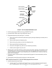
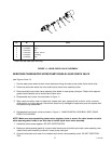
Primary CO
2
Regulator.
(see Figure 2)
Adjust the primary CO
2
regulator by turning the regulator adjusting screw to the right (clockwise) until the regu-
lator pressure reads 80 to 100-psig.
Product Blender Tanks Secondary CO
2
Regulators.
(see Figures 2 and 6)
1. Remove the Unit lower front access panel as instructed for access to the product blender tanks secondary
CO
2
regulators.
2. Adjust the product blender tanks secondary CO
2
regulators, with 60-psi gauges, by turning their regulator
adjusting screws to the right (clockwise) until their gauges read 25 to 30-psig for best textured product.
3. Install the lower front access panel by reversing the removal procedure.