


3-2
SECTION 3
OPERATION
II. COMPONENT INFORMATION AND
LOCATION (EACH OVEN SECTION)
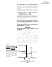
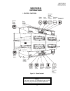
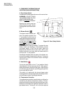
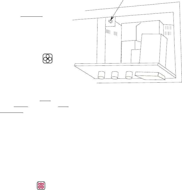
A. Door Safety Switch
Located at the inside upper left corner of the control box.
WARNING: DO NOT TOUCH
THE WIRES GOING TO THIS
SWITCH BECAUSE CUR-
RENT IS ALWAYS PRESENT.
Opening the control panel per-
mits the switch to open, discon-
necting power to all electrical con-
trols.
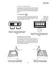
B. Blower Switch
The blower switch has two posi-
tions. The switch must be in the
"I" (on) position for the burner to
ignite, permitting the oven to heat.
The blowers circulate air through-
out the oven and must stay on
during baking and during the cool-
down cycle (above 93°C [200°F])
to prevent blower bearing damage. To protect the two
blower motors and bearings, a thermostatic override
(cool-down switch) is built into the oven. When the
temperature inside the oven is over 180° F (82° C), the
blowers continue to run even after the blower switch is
turned to the "0" (off) position.
Centrifugal switches (built into each of the blower mo-
tors) serve as safety interlocks for the burner. The burner
cannot ignite if either of the blower motors' centrifugal
switches is open.
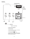
C. Heat Switch
Turning the heat switch to the "I" (on) position initially
starts operation of the oven purge circuit. After approxi-
mately 45 seconds, the pilot burner lights. After the pilot
is lit, the main gas valve opens, permitting gas to go to the
burner and heat the oven.
This switch is in series with the burner blower motor
centrifugal switch, the high-temperature limit safety switch,
and the blower motors' centrifugal switches.
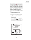
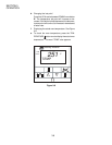
D. Temperature Controller
The temperature controller is a solid-state, on/off type for
maintaining the desired temperature setting. The tem-
perature controller continuously monitors the ovens' tem-
perature and actuates the high-flame solenoid valve in
gas heated ovens. The heat is 'on' for the time required
Figure 3-2. Door Safety Switch