


4-6
SECTION 4
MAINTENANCE
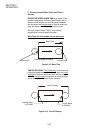
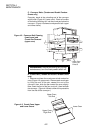
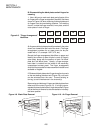
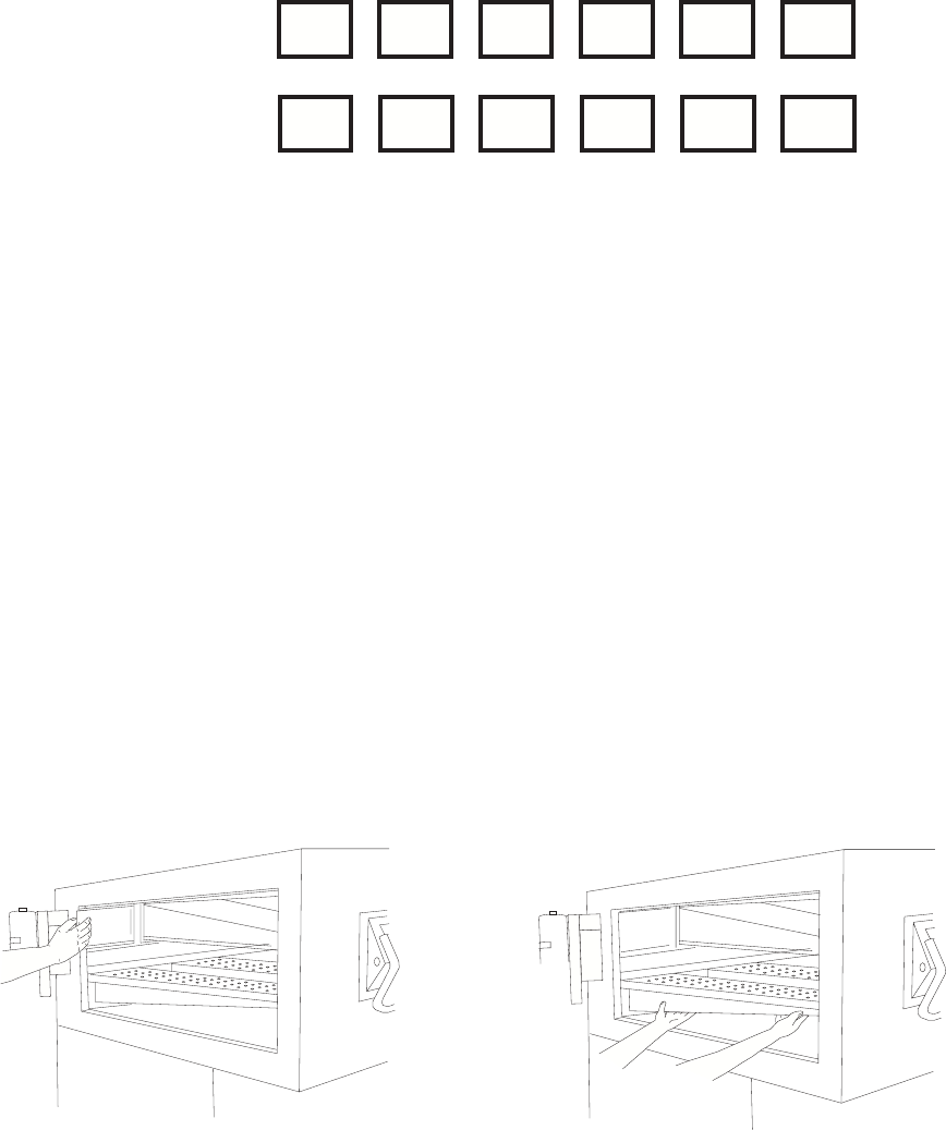
Figure 4-8. "Finger Arrangement"
Identifiers
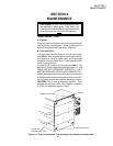
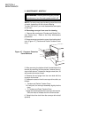
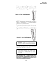
Figure 4-10. Air Finger Removal
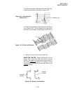
Air fingers and blank plates should be marked in the order
shown, as viewed from the front of the oven. (The finger
arrangement numbers for an
upper
oven can be pre-
ceded with a "U"; example: UB1, UT2, etc.)
Record the finger arrangement identifiers on paper and
identify the number of rows of holes in each air finger's
outer plate, along with the position of each 'full-blank'
plate and 'half-blank' plate. Usually, a finger arrange-
ment label is installed on the inside of the machinery
compartment access panel. The finger arrangement
should still be recorded for instances when the label is not
available or illegible.
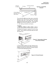
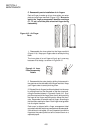
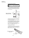
2. Slide each blank plate and air finger along the channels
on the rear baking chamber wall (Figure 4-9), until each
can be extracted from the oven. Prevent twisting or
turning, to avoid interference in the channel(s).
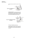
Remove top and bottom air fingers and blank plates from
either end of the oven (Figure 4-10). It is highly recom-
mended that each plate and air finger be marked (Figure
4-8) at the time of removal to aide reinstallation in exactly
the same position.
T1 T2 T3 T4 T5 T6
B1 B2 B3 B4 B5 B6
Figure 4-9. Blank Plate Removal
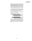
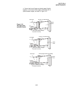
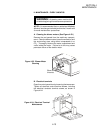
B. Disassembling the blank plates and air fingers for
cleaning
1. Use a felt pen to mark each plate and all parts of the
air fingers with a 'finger arrangement' identifier, like those
shown in Figure 4-8, when removing the blank plates and
air fingers from the oven baking chamber. This marking
should include the finger manifold, inner plate, and the
outer plate of each air finger.