


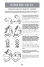
USING YOUR OSTER® MIXMASTER® STAND MIXER
The OSTER® Mixmaster® Stand Mixer has a DUAL MOTOR DESIGN where one
motor located in the head of the mixer drives the beaters while an independent motor
located in the neck of the mixer rotates the bowl for more powerful and optimum
mixing. Please follow the instructions below to use your Oster® Mixmaster® Stand
Mixer:
1. Turn the rotary speed control dial to the “O” position; plug the power cord into the
power outlet.
NOTE: The power indicator light on the speed control dial should now be on.
2. Use the rotary speed dial to turn the mixer on and off and to control the mixing
speeds.
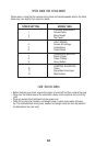
Please refer to the “SPEED GUIDE FOR STAND MIXER” section of this manual for
mixing instructions for several types of mixtures,
Tip: Start mixing at slow speeds and increase speed gradually to prevent
ingredients from splashing out of the mixing bowl. When adding dry ingredients
such as flour, chocolate powders and others, lower the speed temporarily until
ingredients are combined.
Tip: For better results when kneading yeast dough, use speed 1.
SELECTING THE MIXING BOWL SPEED
1. The mixing bowl automatically turns on when one of the 12 speeds is selected in
the speed control dial. For majority of mixing tasks the bowl speed should be set on
the low speed setting “1”. For light mixes requiring maximum mixing performance
such as cakes and meringue, set the bowl speed to the high setting “2” to ensure
the whole mixture goes through the beaters many times. For thick mixes and large
volumes the bowl speed should be set at the low position “1”.
2. When mixing is complete, turn the speed control dial to the “O” position and unplug
the cord from the power outlet.
Note: The indicator light will stay on until power is disconnected from the mixer.
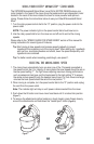
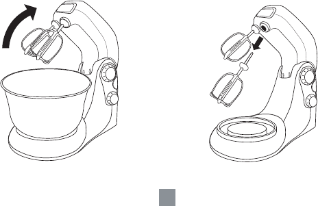
3. Push down the tilt button and move mixer head back until it is locked into position
(Figure 7).
4. To remove the attachments (either beaters or dough hooks), place fingers loosely
around the attachments and hold down the “beater eject” button (Figure 8).
Figure 7
Figure 8
5