


2
Model C300To the Instal ler
Water Coo led Refrigeration Units
(Water Coo led Units Only)
On the back of the unit, t wo additional 3/8” (9.5 mm)
F.P.T. water connections for c ondenser inlet and
outlet have been provided for easy hook- up. 3/8”
(9.5 mm) inside diameter water lines should be
connected to the machine. Flexible lines are
recommended if local c odes permit. Failure to use
adequate size water lines may cause the unit to go
on high head pressure and shut down.
Depending on local water c onditions, it may be
advisable to install a water strainer to prevent
foreign substances from clogging the automatic
water valve.
DO NOT INSTALL A HAND SHUT- O FF VALVE ON
THE “OUT” LINE! Water cooled units are counter
flow and the water s hould flow in this order: First
through the automatic water valve. Second, through
the i nlet located at the bottom of the condenser.
Third, t hrough the outlet fitting located at the top of
the condenser toanopentrapdrain.
IMPORTANT: Water pressures are pre- set at the
factory. Do n ot adjust the water pressure.
Improper water adjustments may c ause operation
discrepancies.
A back flow prevention device is required
on the incoming water connection side. Please
refer to t he applicable N ational, S tate, and local codes
for determining the proper configuration.
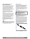
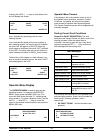
Water Connections
An adequate cold water s upply must be provided
with a hand shut- off va lve. On the back of the unit, a
3/8” (9.5 mm) M.F.L. water connection has been
provided for easy hook- up. A flexible line is
recommended, if local codes permit. A minimum of
25 psi w ater pr essure is required to avoid having the
unit cut out the l ow water pressure switch. A booster
pump must be provided if this pressure is not
available.
Note: Water lines beyond 200 ft. (61 m) require 1/2”
(13 mm) water lines.
INSTALL POTABLE WATER CONNECTION
WITH ADEQUATE BACK-FLOW
PROTECTION TO COMPLY WITH
APPLICABLE NATIONAL, STATE AND
LOCAL CODES.
It is always a good practi ce to have a filter syst em to
improve the quality of the water and to avoid
clogging the operating components.
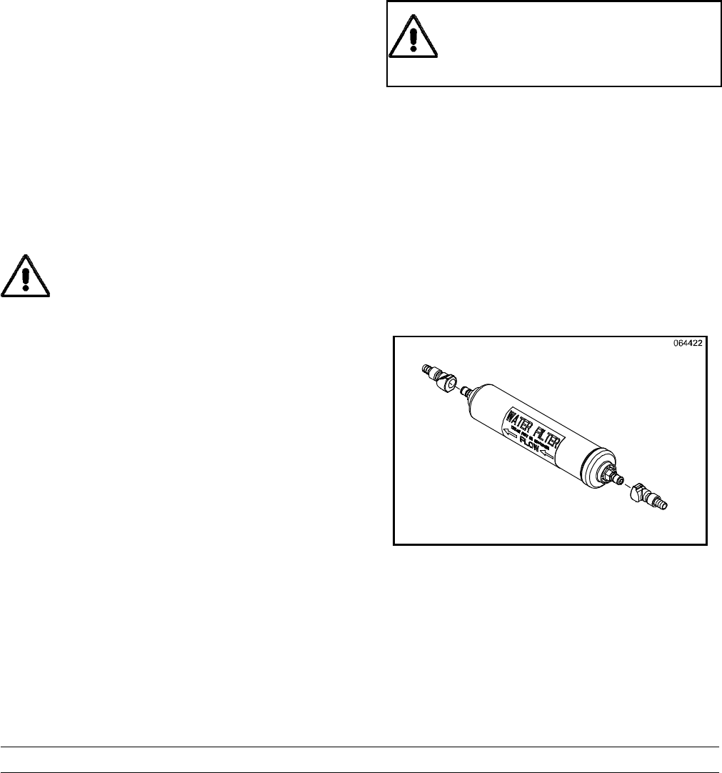
IMPORTANT: The water filter (064422- SER) m ust
be t horoughly f lushed with water before c onnecting it
to the machine. This removes any loose particles
present from the manufacture of the filter that could
clog the flow control. To flush the filter , connect the
inlet end of the filter to the water supply. Position the
outlet end of the filter ov er an empty pail. Open the
water supply. Allow water to flow through the filter
until the water exiting the filter is clear . Close the
water supply. Attach the outlet end of the filter to the
machine. Reopen the water s upply.
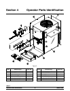
Figure 1