


OVEN SYSTEMS
29
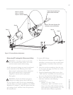
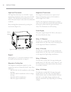
Microwave System
The i5 oven employs two independent microwave
systems (left and right). In the case of an over-
current situation relative to the left system, the F3
fuse will blow. In the case of an over-current
situation relative to the right system, the F4 fuse
will blow.
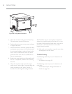
This section contains information about the
following components:
- Capacitors
- Filament Transformers
- High-Voltage Diodes
- High-Voltage Transformers
- Magnetrons
- Stirrer Motor and Assembly
- Wave Guides
This section also contains procedures for:
- Testing a capacitor
- Wiring the filament transformers
- Testing a filament transformer
- Testing a high-voltage diode
- Wiring the high-voltage transformers
- Testing a high-voltage transformer
- Testing a magnetron for an open/shorted
filament
For information on accessing and removing parts,
see the Appendix.
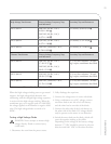
Capacitors
- Capacitor rating is 0.91uF, 2500 VDC for all
60 Hz installations (except Japan).
- Capacitor rating is 1.15uF, 2500 VDC for all
50 Hz installations.
- Capacitor rating is 0.85uF, 2500 VDC for
60 Hz Japan installations.
Testing a Capacitor
DANGER: Never attempt any
measurement of the capacitors while they
are enabled. Lethal voltage will be present.
Measure only in compliance with these procedures.
1. Disconnect the oven from the power source.
2. Fully discharge the capacitor.
3. Isolate the capacitor from the circuit.
4. Check for an open or shorted capacitor by
placing ohmmeter leads between the capacitor
terminals:
- Inconsistent readings = capacitor OK
- Constant infinite resistance = capacitor open
- Constant very low resistance = capacitor
shorted
5. If the capacitor is not open or shorted, set the
meter to measure capacitance and again place
the leads between the capacitor terminals. The
meter reading should equal the label value, plus
or minus 10%. If not, replace the capacitor.
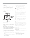
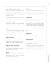
Filament Transformers
For better operation and reliability, the oven
uses separate transformers in order to preheat the
magnetron filament.
The control energizes the filament transformers for
approximately five seconds prior to energizing the
Microwave Circuit via the high-voltage
transformers. When in operation, the filament
transformers supply approximately 3.15 VAC at 10
amps to each magnetron filament. The filament
transformers are controlled via the K1 relay.
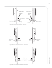
Wiring the Filament Transformers
DANGER: Never attempt to measure the
secondary voltage values of the filament
transformers when they are enabled. Lethal voltage
will be present.
The installation of filament transformers is
straightforward. Filament transformers are wired
in-phase and in-line. Refer to the schematic on
page 51, detailing the proper wiring.
To verify correct wiring (North America),
measure the voltages between terminals
1&2and
1&3on FT1 and FT2. The voltages must be 208
and 240 VAC respectively.