


APPENDIX - REPLACING OVEN COMPONENTS
A-11
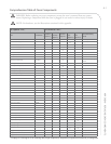
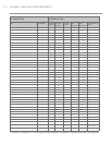
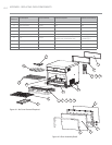
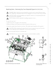
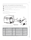
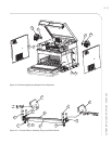
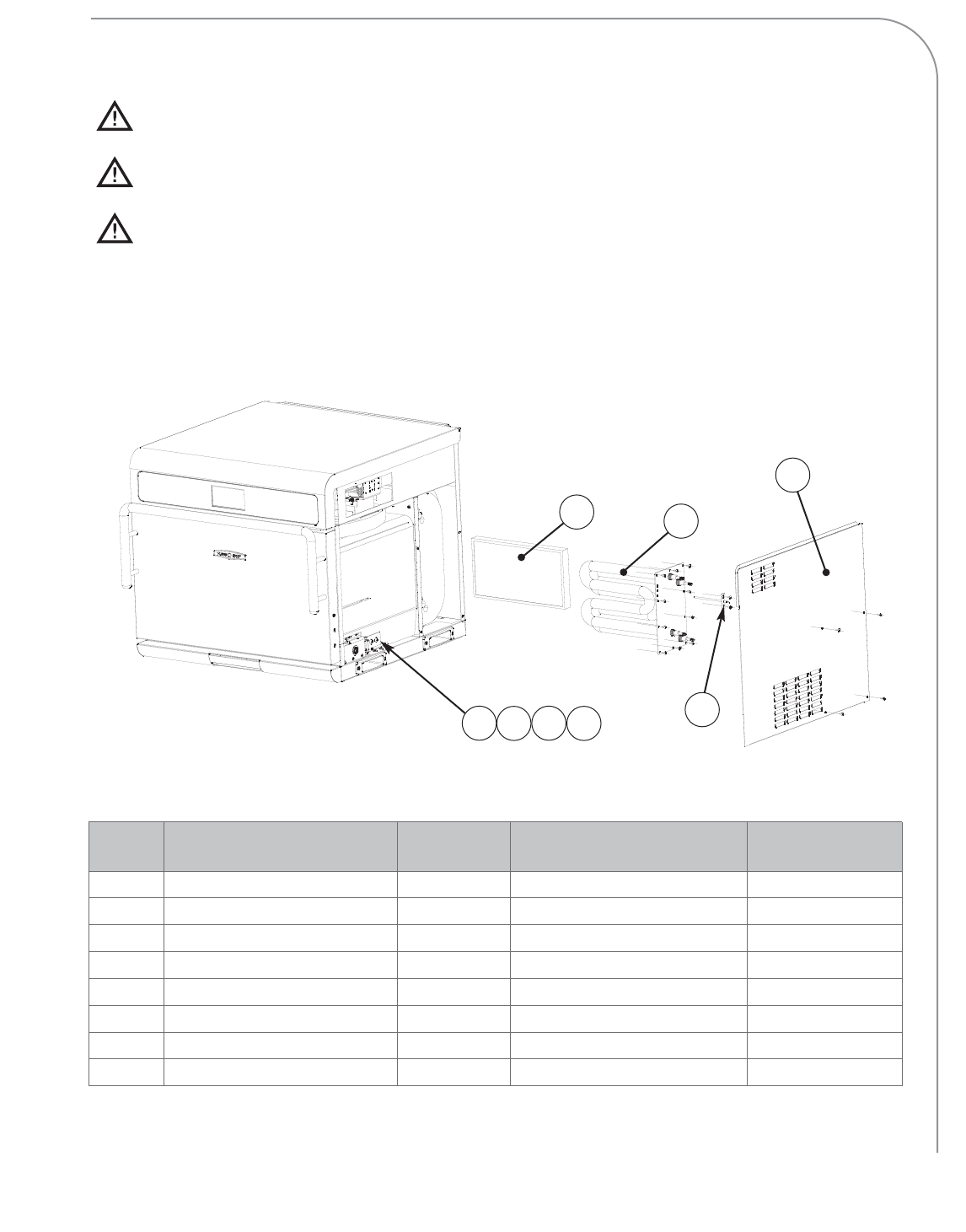
Figure A-9: Removing Right Side Cover Required
Figure
Reference #
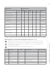
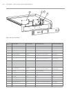
Item Description Item Part Number Hardware Description Hardware Part Number(s)
1 Catalytic Converter I5-9066 None None
2 Cover, Right Side I5-9302 Screw, #8, Serr PPHD, Truss, Black Oxide 101691 (qty 5)
3 Heater Assembly I5-9284 Screw, Sh Mtl #8 x 1/2, Serrated PHTRH 101688 (qty 10)
4 Helper Spring, Interlock Switch* 103599 None None
5 Interlock Switch - Monitor* 102012 Screw, #4-40 x 1”, PPH, Sems 102903 (qty 2)
6 Interlock Switch - Secondary* 102012 Screw, #4-40 x 1”, PPH, Sems 102903 (qty 2)
7 Mounting Bracket, Interlock Switch* I5-9272 Screw, #10-32 x 3/4 lg, PPH Sems, Int Th 102937 (qty 2)
8 RTD, Cook Cavity HHC-6517 Screw, Sh Mtl #8 x 1/2, Serrated PHTRH 101688 (qty 2)
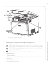
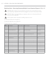
Replacing Items - Removing Right Side Cover Required (Figure A-9)
DANGER: Before replacing any oven component, ensure the oven is removed from any power
source. Replacing a component while the oven is plugged in can result in serious injury or death.
CAUTION: Before removing/installing any component, make sure it is disconnected from the
wire harness (where applicable).
NOTE: Hardware listed is required for installing component to oven.
To remove the right side cover:
1. Remove the screws securing the panel to the oven frame.
2. Remove the right side cover.
* NOTE: For more interlock switch detail, see Figure A-11, page A-13.
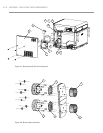
1
3
4
5
6
7
2
8