


OVEN SYSTEMS
33
Control System
This section contains information about the
following components:
- Control board
- Display
- Electrical compartment cooling fans
- Electrical compartment cooling fan thermostat
- Electrical compartment thermocouple
- EMI Filter
- Fuses
- High-limit thermostat
- Keypad
- Magnetron cooling fans
- Magnetron thermostats
- Power Supply
- Relay (K1 - Filament)
- Relay (K2 - Anode)
- Relay (K3 - Monitor)
- Relay (K6 - Voltage)
- Relay (K7 - Mag fan)
- Relay (K8 - Stirrer)
-RTD
- Smart card reader
- Solid state relay (K4/K5 - Heater)
- Speaker
- USB port
- Voltage sensor
- Wire harness
Control Board
The control board controls each electrical compo-
nent of the oven. See page 51 for a schematic. 24
VDC can be measured at pin 2 of the J7
connector.
Display
The vacuum fluorescent display is the primary user
interface.
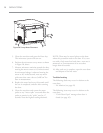
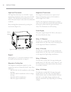
Electrical Compartment Cooling Fans
The cooling fans (located in the rear of the oven)
are actuated by the cooling fan thermostat when
the temperature of the electrical compartment
reaches 120
º
F (49
º
C).
Electrical Compartment Cooling Fan
Thermostat
The cooling fan thermostat actuates the rear
cooling fans when the electrical compartment
temperature reaches 120
º
F (49
º
C).
Electrical Compartment Thermocouple
The electrical compartment thermocouple is a type
“K” thermocouple, which measures the
temperature of the electrical compartment. If the
temperature of the electrical compartment is above
158
º
F (70
º
C), an F6: EC TEMP” fault will
display. The control board checks the temperature
of the electrical compartment once every 60
seconds.
EMI Filter
The EMI filter helps suppress the amount of RF
interference emitted by the oven.
Fuses
All four fuses are 12-amp, class CC.
The F1 fuse (via blue wire) or F2 fuse (via brown
wire) is designed to blow in case of an over-current
situation relative to the following components:
- BMSC motor controller
- Electrical compartment cooling fans
- Filament transformers
- Magnetron cooling fans
- Power supply
- Stirrer motor
The F3 fuse is designed to blow in case of an over-
current situation relative to the left microwave
system (magnetron, high-voltage transformer,
diode, capacitor).
The F4 fuse is designed to blow in case of an over-
current situation relative to the right microwave
system (magnetron, high-voltage transformer,
diode, capacitor).