Technical Information
CVA615 Coffee System
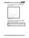
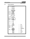
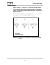
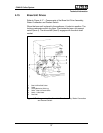
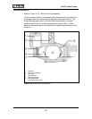
Refer to Figure 4-13 – Components of the Grinder Overload Protection.
The Grinder Motor (Item 1) drives the mounting (Item 3) via the carriers
(Item 2). The rotary force is then transferred via the balls, (Item 5) to the
grinder cone (Item 6).
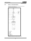
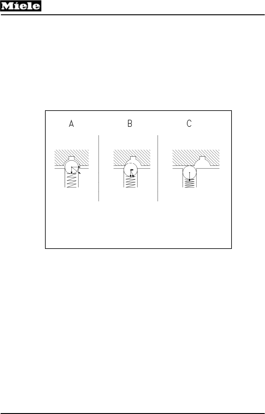
Should the Grinder Cone become blocked the balls are pressed into the
mounting (as shown below in figure C). The drive force is interrupted; and
the worm gear continues to operate via the mounting.
A Normal Operation
B Overload Protection Activated
C Force Transfer Interrupted
Figure 4-14: Ball Positions into the Grinder Cone, Under Different Operating
Conditions
34


