Technical Information
CVA615 Coffee System
10. Remove the plug from the electronic unit.
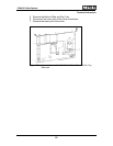
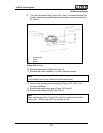
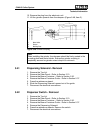
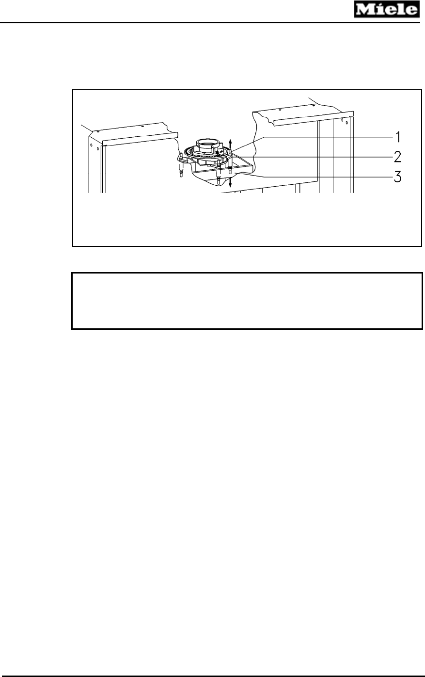
11. Lift the grinder upwards from the dampers (Figure 5-48, Item 2).
Figure 5-48: Grinder Coupling
1 Motor Holder
2 Damper
3 Mounting Plate
Note:
When installing the grinder, the dampers should be firmly seated in the
mounting plate and motor holder. Ensure the grinder coupling is
completely secured so grinder noise is kept to a minimum.
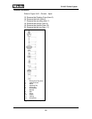
5.41 Dispensing Solenoid - Removal
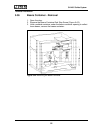
1. Remove the Top Lid.
2. Remove the Rear Panel – Refer to Section 5.10.
3. Remove the Beans Container – Refer to Section 5.36.
4. Remove the Beans Container Guide – Refer to Section 5.37.
5. Press the retainers outward.
6. Slide the Dispensing Solenoid upward out of the guide.
7. Disconnect the electrical connections.
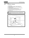
5.42 Dispenser Switch - Removal
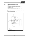
1. Remove the Top Lid.
2. Remove the Rear Panel – Refer to Section 5.10.
3. Remove the Beans Container – Refer to Section 5.36.
4. Remove the Beans Container Guide – Refer to Section 5.37.
5. Remove the Dispensing Solenoid.
6. Press the retainers outwards. Remove the switch.
7. Disconnect the electrical connections.
93


