


Technical Information
CVA615 Coffee System
CVA615 Coffee System – List of Figures (continued)
Figure 5-1: Lid with Screws...........................................................................................47
Figure 5-2: Interference Suppression Filter (Z1) Mounting Location ............................48
Figure 5-3: Rear Panel Removal ..................................................................................48
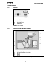
Figure 5-4: Removing the Adjustment Slide Switch Frame (Bezel)..............................49
Figure 5-5: Door Switch (Shown with Appliance Door in Open Position) .....................50
Figure 5-6: Base Plate - Removal.................................................................................51
Figure 5-7: Drip Tray Removal......................................................................................52
Figure 5-8: Overflow Switch Actuator Float ..................................................................53
Figure 5-9: Overflow Switch..........................................................................................54
Figure 5-10: Rear Door Panel - Removal .......................................................................55
Figure 5-11: Fascia Panel Cover Assembly....................................................................56
Figure 5-12: Selector Switch...........................................................................................57
Figure 5-13: Rear View of Front Door with Rear Panel Removed..................................58
Figure 5-14: Components of the Coffee Dispensing Nozzle...........................................59
Figure 5-15: Components of Steam Valve and Steam Valve Switch..............................61
Figure 5-16: Hot Water Valve Components....................................................................62
Figure 5-17: Brew Unit....................................................................................................66
Figure 5-18: Brew Unit Connection Socket Retaining Screw and Locking Tab..............66
Figure 5-19: Brew Unit – Removal for Cleaning .............................................................67
Figure 5-20: Brew Unit Installation..................................................................................68
Figure 5-21: Cleaning Tablet being Placed into the Brew Unit Funnel ...........................69
Figure 5-22: Brew Unit Lubrication Points ......................................................................71
Figure 5-23: Brew Unit Lubrication Points ......................................................................71
Figure 5-24: Moving the Brew Unit to “Home Position”...................................................72
Figure 5-25: Brew Unit in Reset Position........................................................................72
Figure 5-26: Brew Unit – Highlighting the Output Assembly (Covering the Cream Valve)
and Retaining Lugs for Securing the Handle to the Brew Unit Body..........73
Figure 5-27: Rear of the Brew Unit, Highlighting the Funnel Lock..................................74
Figure 5-28: Front of Brew Unit, Showing Spring Location and Holder ..........................74
Figure 5-29: Releasing the Ram from the Bottom of the Brew Unit................................75
Figure 5-30: Brewing Unit Chamber Inside the Brew Unit Assembly..............................76
Figure 5-31: Ram Assembly ...........................................................................................76
Figure 5-32: Front Plate Assembly with Retaining Screw Locations ..............................78
Figure 5-33: Grinder Retaining Screws...........................................................................79
Figure 5-34: Grinder Retaining Nuts...............................................................................79
Figure 5-35: Upper Front Plate Assembly Retaining Screws..........................................80
Figure 5-36: Using a Suitable Item to Keep the Front Plate Assembly Elevated to Access
the Screws at the Bottom ...........................................................................81
Figure 5-37: Removing the Cap to Access the Float in the Water Container .................82
Figure 5-38: Levering Off the Lip Seal Cap ....................................................................83
Figure 5-39: Removing the Lip Seal ...............................................................................83
Figure 5-40: Water Tank Lip Seal Removal....................................................................84
Figure 5-41: Underside View of the CVA615 with Base Plate and Drip Tray Removed .85
Figure 5-42: Removing the Beans Container..................................................................86
6