


Technical Information
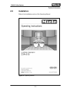
CVA615 Coffee System
CVA615 Coffee System – List of Figures
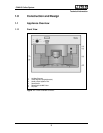
Figure 1-1: Front Overview CVA615...............................................................................9
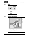
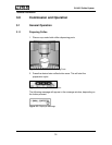
Figure 1-2: CVA Controls..............................................................................................10
Figure 1-3: Interior View of CVA615 with Door Opened ...............................................10
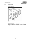
Figure 1-4: CVA615 Product Dimensions.....................................................................11
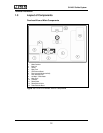
Figure 1-5: CVA615 Overhead View of Components ...................................................12
Figure 2-1: Operating Manual.......................................................................................13
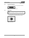
Figure 3-1: Cup Under the Dispensing Ports................................................................14
Figure 3-2: Pressing the Coffee Button.........................................................................14
Figure 3-3: Displayed Message ....................................................................................14
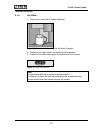
Figure 3-4: Canceling the Preparation Process............................................................15
Figure 3-5: Steam Selector...........................................................................................15
Figure 3-6: Placement of Cup Under the Hot Water Dispenser....................................16
Figure 3-7: Hot Water Button........................................................................................16
Figure 3-8: Grinder Controls .........................................................................................17
Figure 3-9: Adding Coffee Beans..................................................................................18
Figure 4-1: Door Contact Switch (S24).........................................................................20
Figure 4-2: Brew Unit in “Home” Position .....................................................................21
Figure 4-3: Brew Unit Connections...............................................................................22
Figure 4-4: Brew Unit Filters .........................................................................................23
Figure 4-5: Brew Unit Components...............................................................................24
Figure 4-6: Brew Unit, Showing Compressed Coffee “Puck”........................................25
Figure 4-7: Waste Unit Present Switch.........................................................................26
Figure 4-8: Waste Unit..................................................................................................27
Figure 4-9: Water Tank.................................................................................................28
Figure 4-10: Water Level Switch.....................................................................................29
Figure 4-11: Water Level Switch Float............................................................................29
Figure 4-12: Grinder Assembly.......................................................................................31
Figure 4-13: Components of the Grinder Overload Protection .......................................33
Figure 4-14: Ball Positions into the Grinder Cone, Under Different Operating
Conditions...................................................................................................34
Figure 4-15: Coffee Dispensing Components.................................................................35
Figure 4-16: Dispensing Lever........................................................................................36
Figure 4-17: Components of the Brew Unit Drive Assembly, Water Connection and
Present Switch............................................................................................37
Figure 4-18: Brew Unit Drive Assembly..........................................................................38
Figure 4-19: Hot Water / Coffee Heater..........................................................................40
Figure 4-20: Steam Heater .............................................................................................41
Figure 4-21: Water Path..................................................................................................42
Figure 4-22: Water Valve (Disassembled)......................................................................44
Figure 4-23: Power Electronic Board..............................................................................45
Figure 4-24: CPU (Control) Electronic ............................................................................46
5