M2540-92000-01 A M2540 Ultrasound System Field Service Manual Page 21
Specifications: Connection and Communication Specifications
Connection
and Commu-
nication
Specifications
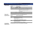
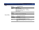
The following tables list the communication and connector specifications of the M2540A.
System I/O
Ports
PC Ports
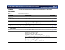
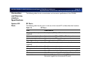
The following table lists the ports on the rear of the internal PC and describes their locations.
Table 2-5 PC Ports
Port Specification
Composite video output
(optional)
1
Female phono (RCA) on TV and video converter board
S-Video output (optional)
1
4-pin mini circular DIN on SVGA to TV video card
S-Video input (optional)
1
4-pin mini circular DIN on video capture card
Print trigger output 3.5-mm phone jack on APIO board
VCR audio output (line out)
(optional)
1
Green 3.5-mm stereo phone jack on sound card
VCR audio input (line in)
1
Blue 3.5-mm stereo phone jack on sound card
Microphone Pink 3.5-mm stereo phone jack
Speakers Green 3.5 mm stereo phone jack to system speaker amplifier
Monitor 15-pin D connector on graphics adapter board
Foot switch 9-pin female D-sub connector on the APIO board that carries
foot switch signals from the external I/O panel


